
Edit an Assembly
You can perform the following editing operations when creating an assembly or later:
- Copy, cut, paste and delete a part
- Move part, rotate
- Define geometric constraints for parts
- Use a dimension as a constraint in the assembly
- Delete a Constraint
- Edit a part, model a new part
- Save a part as a new document
Copy, Cut, Paste, Delete a Part
Copy the part imported into to the assembly, and position it. Select the part and the Clipboard >  Copy function, or press the Ctrl+C keys.
Cut the selected part, and position it to the new place. After selecting the elements, select the Clipboard >  Cut function or press Ctrl+X. Paste the copied or cut part into the assembly by selecting the function Clipboard >
  Paste or by pressing Ctrl+V, and then position the part.
Delete a part by selecting the Delete function or pressing the Delete button.
Move part, rotate
Move the part selected in the assembly, and position it to the new location. After selecting the part, select the Move function. Other parts in the assembly than the part you started with can also be moved by dragging.
Define geometric constraints for parts
You can position the parts in an assembly by using geometric constraints. You can add constraints between parts when creating the assembly, and after that add new parts, define constraints, etc. Define the constraint to two parts at a time.
 Add Geometric Constraints for Parts in an Assembly
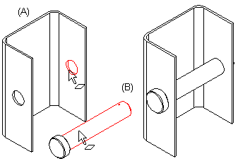
For example, select two parts in the assembly, parts (A) and (B). Select the Concentric constraint. Select the cylinder face on both parts as the element. The parts will be positioned as follows:
Use a dimension as a constraint in the assembly
Distance and angle dimensions can be determined as constraints for the parts in the assembly. These dimensions can be used to control the direction and position of the parts in relation to each other.
Delete a Constraint
You can view the constraints defined for the parts in the assembly by viewing the assembly model. You can delete the constraint by first selecting the symbol of the part in the assembly tree, then select the constraint and the Delete function.
Edit a part, model a new part
While creating an assembly, the parts in the assembly can be edited, and new parts can be modeled. You can select part in the assembly, open it in a working window, edit it or model it further.
You can model a new part in an assembly. The existing geometry of the assembly displayed in a wire frame view can be used to assist in drawing the sketch. Draw a sketch, create a feature and continue modeling until the part is finished. Accept the part, so it will be saved in the archive and refreshed in the assembly. Position the new part in the assembly by using geometric constraints.
Save a part as a new document
You can save a part selected from an assembly into the model archive as a new part (document). If necessary, you can also replace the part selected from the assembly with a new part, retaining the geometric constraints of the assembly, or leave the assembly unchanged.