
View Constraints in Working Window
Geometric constraints are displayed as dimension constraints and graphical symbols between elements in the working window. The dimension constraint or symbol indicates that there is a geometric constraint between the elements.
- Press the F9 key to toggle the visibility of the symbols.
- Select
 Drawings, models and select
  Show Constraints, and select OK. Remove the selection, if you don't want to see constraints.
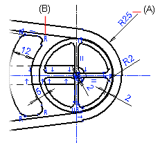
As an example, geometric constraints in the 2D drawing.
- Dimension constraint (A).
- Other geometric constraints are displayed as a graphical symbol (B).
The dimension constraint and the displayed symbol are highlighted in blue, when the geometric constraint is in effect.
Geometric constraints are displayed as follows:
-
Part Model Sketch
Dimension constraints and the graphical symbols of geometric constraints are displayed in a part model sketch. The constraints are also displayed in the feature tree of the part.
In a 3D sketch, only the dimension constraints is displayed.
Visibility of Geometric Constraints in a Part Model Sketch
Feature Tree of a Part
Feature Tree Symbols and Conventions -
Assembly Model
The geometric constraints of an assembly model are not displayed in the model. The constraints are displayed in the assembly tree.
-
Drawing
Dimension constraints and the graphical symbols of geometric constraints are displayed in a drawing.