
Dimension Data to Be Updated Using Named Dimensions
You can collect named dimensions from a 3D model in parts list data. A named dimension is a dimension for which a variable has been defined in the Formula field. For example, you can name the distance dimension of a model sketch or a dimension of a feature. In a model drawing, you can also name dimensions, whose data can be collected in the parts list.
The data of the named dimensions is collected in the parts list in a specific order. When collecting a parts list, the named dimensions are collected first from the 3D model and then from the model drawing. The parts list data is updated based on the collected data.
You can name dimensions in a model drawing as follows:
- You can add several named dimensions to the different projections of a drawing. You can select dimension elements from a drawing projection but not any lines you have drawn.
- In a model drawing, add variables in the Formula fields for those dimensions whose data you want to collect in the parts list.
- Refer to the variable name in the part properties and material data. If the variable name in the Formula field of the dimension properties is A, for example, you can refer to the variable value in the material data by adding hashes to both sides of the variable name: #A#. You can add several variables to the same field, e.g. #A#x#B#x#C#, where the variables A, B and C are named dimensions.
 If named 2D dimensions are used in a drawing, the dimension data automatically calculated in the model is ignored. For example, if you create a sheet-metal part and a drawing of it and add named dimensions for creating the parts list, the preform dimensions that are otherwise calculated automatically for the sheet-metal part are not output to the drawing. This also applies to the named dimensions of features.
Vertex automatically calculates the preform dimensions (Preform/Shape) and area (Quantity) of a sheet-metal part and composite sheet based on certain conditions, and the data are collected on the parts list. For more details, see Model a Sheet-Metal Part and Model a Composite Sheet.
The data of the dimensions named in a model drawing are collected on the parts list only if you select the Collect Parts List function in the 2D drawing.
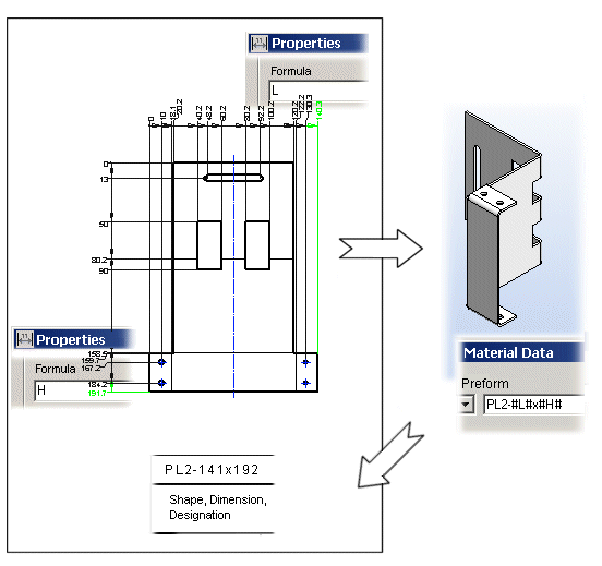
Example – Dimensions named as preform dimensions in the drawing
You want to define which dimension data will be collected and in which order they will be shown in the parts list in a model drawing,. For example, you want to collect the preform data of a sheet-metal part on the parts list in a specific order.
Define the dimension data to be updated as follows:
- Create a drawing from the model and add a sheet.
- Add the dimensions you want to name to the model drawing.
- You can add dimensions to the different projections of a drawing.
- From the drawing projection, you can select dimension elements, the lines of which are created when you make a new drawing based on the model or add a projection to the drawing.
- Name the drawing dimensions as follows:
- Select a dimension from the drawing and the Properties function.
- Define a variable for the dimension in the Formula field of the dialog box.
- Click OK.
- After naming the dimensions, activate the model window.
- Fill in the material data for the part in the item data. Refer to the name of the dimension variable in the field by adding hashes (#) on both sides of the variable name. You can used named dimensions for updating the Preform data, for example.
Example – Contents of the Preform field: PL2-#L#x#H#. The variables L and H are named dimensions.
- Update the parts list data of the drawing by selecting the
 Collect Parts List in the drawing.
