General Information About Sheet Metal Part Modeling
Sheet-Metal Design
General
- Sheet metal parts refer to parts made by cutting and bending sheet metal, which can be used to produce flattened drawings for machining tools.
- In Vertex G4, sheet metal part modeling tools need the add-on option Sheet Metal Design. In Vertex G4 Plant, the option is always included.

How to start a sheet metal part
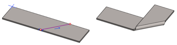
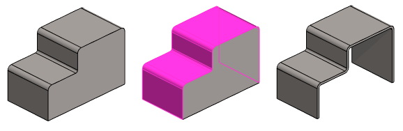
- Sketch a line or chain of lines and extrude it into a sheet metal part.
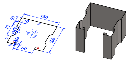
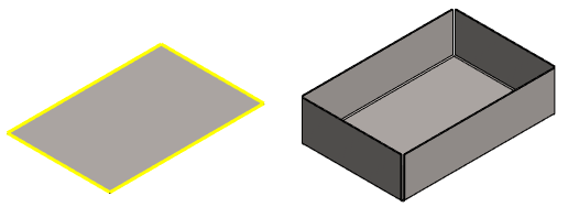
- Sketch a "piece of sheet metal", extrude it to the thickness of the sheet metal, and then convert the part into a sheet metal part.
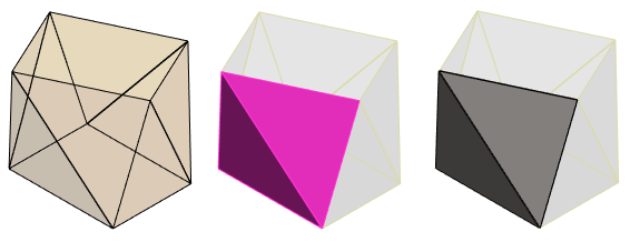
- Get a suitable shape as the first feature of the part from the Sheet_metal library.
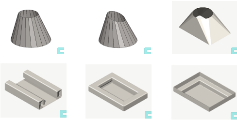
- Model a part where planar surfaces and cylinder surfaces (rounds) alternate and use the function Tangential Offset.
- Use the surface of another (jig) part in the assembly by copying it with the function Faces > Copy faces, and convert the surfaces to a volume model and further to a sheet metal part.
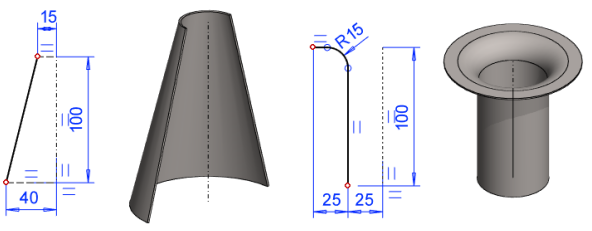
- Sketch a line and revolve it to a sheet metal part.
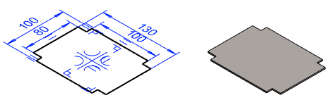
- Generate a sheet metal model from a 2D drawing.

Tools related to sheet metal parts
Add Bend Radius
- Add Bend Radius
- The function should be used when the line chain has been extruded into a sheet metal part without the rounds required for bending.

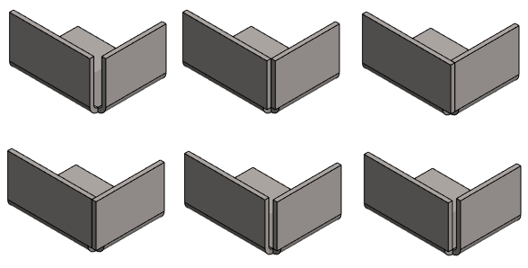
Add Flange
- Add Flange
The function adds flange features to selected edges of a sheet metal part.
Trim Edges
Trim a Corner
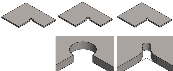
Open a Corner

Cut a Sheet

Step Bend

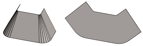
Flatten the model
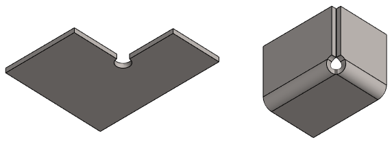
Rebend a flattened model
- Rebend a Flattened Part
- This function is used when the 3D-flattened model has e.g. a cutout extrusion to the bending area or a corner has been trimmed (in the image).
Bend a sheet with a sketch line