
Assembly Installation Drawing - Display Reference Parts
The purpose of use
In the installation drawings, you want to show the connection of the model (part or subassembly) to the higher-level assembly structure.
- In this case, the geometry of the part or the parts of the assembly is represented by normal lines.
- The lines of other parts, i.e. related reference parts, are often wanted to be represented with other line types, e.g. colored dot-dash lines.
General
- In the initial situation, the Vertex desktop has an assembly model and you are editing its sub-assembly, in the drawing of which you want to represent some parts of the main assembly or its other sub-assemblies.
- The reference parts are drawn with default line properties or line types whose properties you can select.
- You can add reference parts to the drawing, remove them from it or edit line properties later.
 Reference parts are displayed in the drawing but they are not incorporated in the product structure of the assembly.
Selecting Parts Displayed in the Drawing from the Assembly
- Open the assembly containing the part or sub-assembly whose drawing you want to retrieve reference parts for.
- Select the model whose drawing you want to process from the feature tree.
- Select the context-sensitive function Edit.
- In the feature tree, click the symbol of the part or sub-assembly to be edited.
- Select the context-sensitive function Other Functions> Reference Parts to Drawings.
- Select the first reference part or select multiple parts as reference parts while holding down the Ctrl key.
- Accept selected parts with the Confirm function. (Confirm = V key, middle mouse button or the context-sensitive function
 OK).
OK).- The program opens the dialog box Reference Parts to Drawings, and lists reference parts there.
- Add or remove parts from the reference parts list
- Click Insert, If you want to add reference parts.
- Select the part or parts to be added.
- Confirm the selection.
- Select a part from the list, and click Delete if you want to remove a part from the list
- Click Insert, If you want to add reference parts.
- Define the line types for reference parts
- By default, lines are drawn as if they were the model’s own lines, i.e. as shape lines, etc.
- First, select the part or parts from the list whose lines you want to affect.
- Click Drawing.
- The program opens the dialog box Line Properties.
- Click the
 button in front of the line type to open its properties.
- The program opens the line properties: Layer, pen, line type, line gap and color.
- Select the property you want to affect.
- Use the preset button to select a new property for the line.
- OK accepts the new properties selected for the line styles of the reference lines
- Open the model drawing or create a new drawing.
 New Drawing of a Model
- Reference parts are drawn in the model drawing.
- Save the drawing with the Save function.
- Return to the main assembly, for example with the context-sensitive function
 OK.
OK.
Opening the same drawing later
The next time you want to open the same drawing, so that its reference geometry remains in the drawing.
- Open the model where the reference geometry was defined for the part or sub-assembly drawing.
- Edit a part or sub-assembly that has reference parts in the drawing.
- Open a drawing of a part or sub-assembly.
Note:
- If you open a drawing from an archive or open an assembly from an archive that has reference parts in the drawing, they will be removed when the drawing is updated.
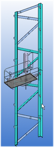
Example
The reference parts are drawn as magenta dashed lines in the model drawing
| 3D | 2D |
|
 |
Adding Reference Parts to a Drawing and Removing Them
See steps 1...9 above
Defining the Properties of Reference Geometry Lines in Settings
By default, the geometry is drawn with the line properties defined in the settings.
You can edit the line properties as follows:
- Select
 Administrator's View.
 - Select the Keyword group geomprop.
- Select Lineproperties.
- Select the keyword: Common Line Properties.
- Define the line properties in the Value field: Layer (1), Line width (2), Line type (3), Scale (4), and Color (5).
For example, REF_PART 2 0.18 1 1 182
- Select OK.