
Projections of a Model Drawing
General
- The first projections are generated for the drawing at the same time you create the drawing from the model.
- Add new projections to the drawing, if necessary.
- You can create section and detail view projections based on projections already in the drawing.
- You can cut "pieces" out of the projection.
- The drawing has a so-called projection tree, which allows you to perform some actions.
- Take a closer look at Projection Tree of a Drawing
Adding a projection to a drawing and most operations on projections are only possible when you have opened the drawing through the model and the model is also on the desktop.
New Projection of a Model
You can add a parallel projection, sheet-metal flattening, isometric, or other projection to a model drawing. The new projection is created based on the chosen viewing direction.
- From the ribbon bar Drawing | Tools | Projection >
 Projection.
 - With the context-sensitive function Projection.
- For more details, see Add a Projection to a Model Drawing
New projection using an existing projection
The function can be used to create a top, bottom, right or left projection from the selected projection.
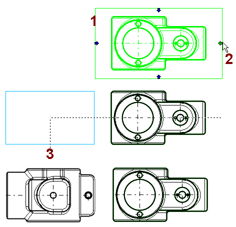
- Select a projection.
- Four arrows appear on the edges of the projection to indicate the direction of views.
- Click a direction arrow.
- Select the location of the new projection.
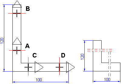
Section View
- With one straight line.
- The line can be clicked by two points or
- The line can be clicked from a previously drawn line.
- With a rectangular polyline.
- This allows for the formation of a half-section as shown in the image.
- With a polyline.
- For more details, see Section View.

Partial Section View
- A projection can only have one partial section view.
- Draw a continuous closed polyline to delimit the section.
- Select a projection.
- Select the context-sensitive function
 Partial Section View.
 - Click the line delimiting the section.
- Specify the cutting depth in the model window that opens.
For more details, see Section View Using a Line

Detail View
- A detail view can be rectangular or circular (ellipse).
- Projections of the model drawing and independent drawing have their own functions for creating detail views. For more details, see

Cut a Projection
Projection cutting can be done for a projection of a model drawing or, for example, for two adjacent projections at the same time.
- Select the projection or adjacent projections to be cut.
- Select the context-sensitive function
 Cut View.
 - Click the location of the horizontal section lines.
- Select Confirm (V key, middle mouse button or the context-sensitive function
 OK.)
OK.) - Click the location of the vertical section lines.
- Select Confirm
See details Cut a Projection.
Projection Detail
- Projection areas of different scales can be created for the drawing.
- See details Detail Projection Data.
- Projection areas can be defined for a cut drawing in such a way that the dimensions added to the drawing show the dimensions of the long object.
- A long drawing can be cut into two or more projection areas.
- See details Cut Projection Detail.
Projection Detail
Importing a 3D View in the 2D Window
- For more details, see Import 3D Model as a Drawing into 2D Window