
Projection Tree of a Drawing
The projection tree helps you to view and edit projections of a drawing that has been created from a part or an assembly with this software.
- In the project tree, you can select, for example, projections, assembly structures, reference drawings and raster images and assign the functions of the context-sensitive menu to them.
Contents of the Projection Tree
- Projections
-
- Projections can only be found in drawings generated from models and opened from the model.
- The projection label consists of the text VIEW, a running number, and the label of the configuration.
- To list the projections of the drawing, click the button
 under
under  Projections.
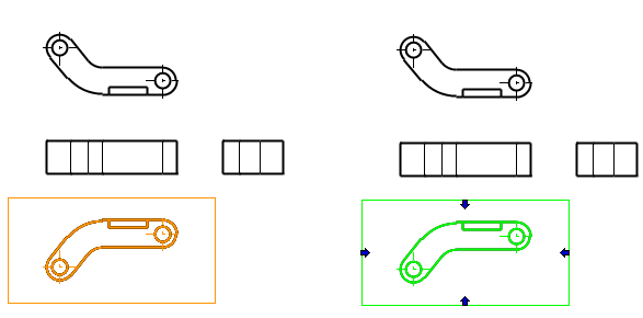
- Select a projection
 by clicking it.
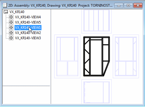
- Reference Drawings
- Reference drawings are mostly used with independent 2D drawings, in which case the reference drawing is partially limited or fully displayed in the main drawing.
- If the drawing has reference drawings, there is the button in front of
 Reference Drawings
 - Click the button to get a list of reference drawings.
- Raster Images
- Raster images are pixel format images that can be used in a drawing if needed.
- If the drawing has rasters, there is the button in front of
 Raster Images
 - Click the button to get a list of raster images.
- Feature tree of an assembly model
-
- The model feature tree can only be found in drawings generated from models.
- Click the button to open the feature tree.
