Assembly Geometric Constraints
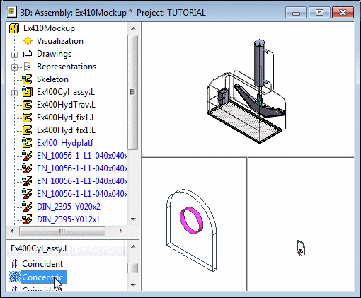
The geometric constraints of an assembly can be found beneath the assembly tree. When you select a part from the assembly tree, only its constraints are shown beneath the tree. If you select the label of the main assembly, all geometric constraints will be presented in the list.
Red color of the geometric constraint indicates the constraint is unsolved in the assembly. Disabled constraint is displayed in matte in the lower frame of the assembly tree. Also, the constraints that cannot be solved because the parts are fixed are indicated by gray color and the text (Fixed) is after the constraint’s name.
The elements connected to a geometric constraint are highlighted in the model when you select the geometric constraint. The numeric value of the constraint is displayed inside parentheses.