Define the light properties: intensity, is the light on or off, color, location, direction
and shadows.
Dialog Box Options
- On
- Switch the light on (default) or off.
- Use as OpenGL light
- Switch the feature on or off (default). If you use the light as OpenGL light, it is seen
also in workspace in addition to the Rendering space.
- Name
- You can name the light. It will be easier for you to recognize the light in the object
tree and the light table.
- Intensity
- The intensity can have values 0-1. If you change the value, you can see the change of
the intensity in the model at once.
- Light falloff
- You can select this property for a point light and a spot light. Select one of the
following:
- Constant - Default value. The intensity of the light does not decrease when the
distance increases.
- Linear - The intensity of the light is halved when the distance is doubled.
- Square - The intensity of the light is reduced to one quarter when the distance is
doubled.
- Light color
- White light is the default. You can define the color in the following ways:
- Enter the color's RGB value in the Red, Green and Blue fields.
- Click the Palette button and click a color in the palette. You can adjust a luminous
of a color with the slide switch. Accept the color selection. The selected RGB value
of the light color is displayed in the dialog box.
 Selecting RGB Color
- Shadows
- Select whether the light creates shadows or not. Edit the variable values of the shadows
by clicking the Values button. You can edit three variables:
resolution, softness, and quality. Select a new value from the list or enter a numeric
value in the field. Following numeric values are possible:
- Resolution can have a value between 0 and 2048. At resolution 0 the shadows will be
sharp.
- Softness can have a value between 0 and 5.5.
- Quality can have a value between 0 and 9.
- The best and sharpest image is achieved by using the values Resolution=0, Softness=1 and
Quality=9.
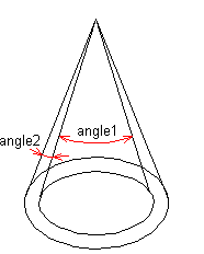
- Light cone
- You can select this property for a spot light. Click the Values
button, and enter numeric values in the fields. The numeric values are as follows:
- Light cone angle - Defines the angle of the light cone in degrees (angle1).
- Light cone delta angle - Defines the half-light area in degrees (angle2).
- Beam distribution - Defines the distribution of the light beams. With large values
such as 8, the light beams are concentrated in the middle of the light cone. With
small values such as 0 and below, the light beams are concentrated at the edges of the
light cone.
- Light place and direction
- You can define the position and direction of a light in different ways, depending on the
light type.
- Point LightYou can only define a position for a point light. Click the Position
button and select the position in the model. Point light illuminates spherically in
all directions. Its beams begin from the position point and are evenly
distributed.
- Spot LightYou can define both the position and direction for a spot light. First,
click the Position button, and click a point in the model. After this, click the
Location button, and click a direction point in the model. The beams are spread
conically from the position point towards the direction point. You can define the
properties of the light cone under Light cone.
- Distant LightDefine the position and direction of distant light by moving the
Rotation and Height sliders.Rotation is the direction of the incident sunlight. It can
be adjusted 0 to 360 degrees around the model. If the value is 0, the direction of
incidence is left. Larger values rotate the direction of incidence
counter-clockwise.Height is the altitude angle of the light (the sun) (-90) 0 to 90.
With a Height value = 0, the sun is to the level of the horizon. When the Height = 90,
the sun is straight above. In Finland (Helsinki), the highest point the sun shines
from is about 53.5 degrees at the summer solstice. In practice, lower altitude angles
are more useful for rendering.If you wish, you can set the position and direction
coordinates of the light to zero, in which case the incoming direction of the light is
relative to the viewing angle. It is not necessary to edit the incoming direction of a
relative distant light, when the viewing angle changes.
- The feature Binding is not used in the Vertex BD
application.
- Render
- The model in the working window will be visualized, when you click the button.
- Advanced
- The function opens the Light Edit dialog box in which you can edit the shader properties
of the light.
-
Light Shading
Properties
