
Wall Panel Accessories
Framer
You can create joints and add joint components between wall panels. The joint component data is also collected in the material report. Before adding joint components, you must generate the panel drawings.
- Select Classic Wall Framing | Panel |
 Accessories.
 - Select the joint type from the joint component library with the Vertex Browser. The
folders and joint components in the library and the application development program
determining how the joint is formed are customer-specific. The following joint types are
included in the basic software delivery:
- Wall panel seams
- Wall panel stacks
- Wall panel anchors
- Select Confirm. The browser reopens and you can select another joint type.
Joint components for panel drawings
Joint components are added to the building's floor plan. You can also make the joint components visible in the panel drawings by setting the following keyword in the BDSXX keyword group:
wpnlconnmacmode= 1
If you move a joint component in a wall panel drawing, the change will be automatically updated in the floor plan and the connected wall panel's panel drawing, when you close and save the wall panel drawing. In the same way, if you move a joint component in the floor plan, the change is updated to the wall panel drawing.
 Note
Note
- Depending on the selected joint type and customer fitting, you have the following
functions available when adding joint components:
- Click the Connected button to have the codes of the wall panels connected to the first wall panel displayed in a list. Select the code of the wall panel to be connected from the list.
- Click the Locate button to have the locations of the joint components automatically determined by the application development program.
- If necessary, you can change the locating point by clicking the Loc.Point button.
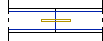
Wall Panel Seams
You can create the following joint types:
- Wall panel parallel seam
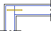
- Corner Connection
- Wall panel tee seam

- Wall panel free end

When you have selected the joint type in the browser, do as follows:
- Select the end of the first wall panel.
- Do either of the following
- Select the end of the second wall panel.
- Click the Connected button to have the codes of the wall panels connected to the first wall panel displayed in a list. Select the code of the wall panel to be connected from the list.
- If you chose the Free End joint type, select the Confirm function.
- Depending on the customer fitting, you can define parameters for the joint components.
- If you have already added joint components to the selected wall panels, the program will
query you: 'Delete old connectors?'
- Select Delete, when you want to delete the old joint components and add new ones.
- Select Ignore, when you want to retain the old joint components and add new ones. If you have moved old joint components in the wall panel drawing, their locations will remain unchanged.
- Quit by pressing the Esc key.
- Update the panel drawing by selecting Yes in the message box.
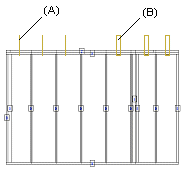
Wall Panel Stacks
Creation of these joint types requires that there be a wall panel with a wall panel drawing on the floor above or below the selected wall panel. The center lines of the wall panels must be coincident. You can create the following joint types:
- Wall panel stacked bolts (A)
- Wall panel stacked holes (B)
When you have selected the joint type in the browser, do as follows:
- Select a wall panel.
- Click the Connected button to have the code of the wall panel above or below the first wall panel displayed on a list. Select the code of the wall panel to be connected from the list.
- Do either of the following:
- Click locations for the joint components one by one in the floor plan and select the Confirm function.
- Click the Locate button to have the locations of the joint
components automatically determined by the application development program.
 Requires a customer fitting.
- If you have already added joint components to the selected wall panels, the program will
query you: 'Delete old connectors?'
- Select Delete, when you want to delete the old joint components and add new ones.
- Select Ignore, when you want to retain the old joint components and add new ones. If you have moved old joint components in the wall panel drawing, their locations will remain unchanged.
- Quit by pressing the Esc key.
- Update the panel drawing by selecting Yes in the message box.
Wall Panel Anchors
When you have selected the joint type in the browser, do as follows:
- Select a wall panel.
- Click a location for the joint component. As a default, the locating point of the joint component is in its center point and the joint component is locked for movement along the wall panel's center line. If necessary, you can change the locating point by clicking the Loc.Point button or pressing the F8 key. This will change the locating point by turns to one of the four corners of the joint component's 2D presentation.
- Select Confirm.
- Quit by pressing the Esc key.
- Update the panel drawing by selecting Yes in the message box.