
Compare Components of a Layout Drawing to a Parts List
- Compare components to a parts list.
Compare the device data of the device symbol in the diagram to the layout drawing of the box in question.
- When comparing you can also add a cable trough in the Layout drawing.
 Adding a Bar and Cable Trough to a Layout
Drawing
Adding a Bar and Cable Trough to a Layout
Drawing
Collect Parts List
- Open both in the working window:
- Layout drawing
- Circuit Diagram
- Make sure that the same position label occurs in the diagram (in devices) and in the
Layout drawing. For example, defined as position areas or in the archives cards. As an
example, +SK1:
- In the archives card of the drawing sheet in the circuit diagram.
- In the archives card of the Layout drawing.
- Activate Layout-drawing and link the parts list to the layout drawing.
- Select
Drawing Data
- Fill in the name of the parts list in the filed of the archives card Cable Harness. As an example, ABB00100.
- Select OK.
- Select
- Select
 tab, Reports group,
 Parts List.
Select following:
Parts List.
Select following:- Output format LAYOUT PARTSLIST.
 Collect
from all sheets
Collect
from all sheets- Roll-out to end
- Select OK.
Compare Components To a Parts List
- Select
 tab,
tab,  Part Number group,
 Compare to Parts
List.
Compare to Parts
List.
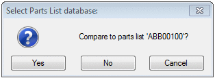
- Select Yes.
You will see the list of components missing from the Layout drawing.
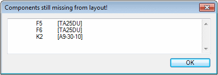
- Select OK.
Browse components of active layout position (SK1) window is opened.
You will see the number of components in the diagram (columnQty) and the number of components in the Layout drawing (LayDiff).
 If in the lines of column
LkmLayout is displayed a mark *0, the
component is missing in the Layout drawing.
If in the lines of column
LkmLayout is displayed a mark *0, the
component is missing in the Layout drawing.
- Select the row containing mark *0 and click the
 button.
 - Select a position for the component in the Layout drawing.
After this, the color of the marking turns from black to red in the field. 1

- Select OK.
- Save changes by clicking Save in the drawing.
- Select the location. You can add several bars and cable troughs at the same size in this view.
 Note
Note
- If there is extra part data in the Layout drawing, the Extra Comp button is activated. By clicking the button, you can check which ones are extra compared to the circuit diagram.