
Edit Assembly with Dimension Table (3D)
Use this function for:
- To edit the geometry of a library component and the geometric dimension constraints between parts in an assembly.
- Create Table IDs This requires that variables have been defined for dimension constraints of an assembly and geometry of a component. In addition, editing values of the constraints is allowed, not only using table ID's.
- A library component added to an assembly is associated with the original part, but the component can still have assembly-specific dimensions.
- In an assembly dimension table such component is displayed, which features are not controlled by the table ID's of the dimension table. Values of the variables are edited by entering a new value in the dimension table field. Changes made to the original geometry (part) of such components must be separately refreshed in the assembly.
- Components edited using table ID's are automatically refreshed and can be opened for editing with the Edit function.
Edit the assembly:
- Select the label of the assembly from the assembly tree.
- Select the context-sensitive function Dimension Table.
- Select one of the following:
- Sorted by Parts.
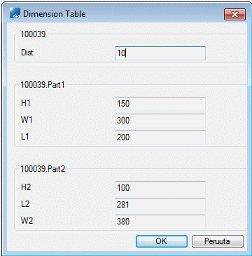
The dimension table displays the components (parts) which dimension constraints have variable definitions, and components, which variable values can be edited in the dimension table.
The assembly ID (100039) and the variables of the dimension constraints between parts are displayed in the dimension table. The component's variable data is displayed separately in the table (100039.part1), with the assembly ID and the component ID separated by a period (.). The variable data of a profile part is displayed in a corresponding way, with the assembly ID and the profile type separated by a period.
- Only Variables.
All variables are listed in the dimension table. If an assembly has several variables with the same name, the variable is displayed in the table only once. The variable controls the change in all components in which the variable in question is used.
- Sorted by Parts.
- Edit the dimension table as follows:
- Edit the value in the dimension constraint variable field.
- Edit the value in the dimension constraint variable field.
- Create new table ID's for a library component.
- Click OK.

- If
 Selected variable values only from list is selected in the dimension table of a component, the component is edited using table IDs, and editing of variable values is blocked. This kind of library component's variables is not displayed in the assembly dimension table. For example, the System folder components.
 - If in the components dimension table is not selected
 Selected variable values only from list, you can refresh the geometry changes in the assembly by selecting the part in the assembly model, and select the Change function. The variable values will retain.