
New Drawing of a Model
Create a new drawing of a part or assembly.
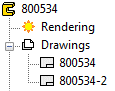
Drawing Label
- When you create the first work drawing, the drawing will inherit some of the model's archive data.
- If you edit the model's archive data, the changes will not be updated to the model drawings.
- The label of the first drawing is the same as the label of the model.
- To the next drawings is added number label.
For example:
 The number of drawings is not limited.
Create a New Drawing of the Model
- Open a part or an assembly in the working window.
- If necessary, activate a certain configuration of a model, which you wish to create a new drawing.
- Do either of the following:
- Double-click
 Drawings in the tree.
 - Move the cursor on Drawings, and select the context-sensitive function New Drawing.
- Double-click
- Select the properties of the new drawing in the New Drawing dialog box.
For example:
- Projection. The default setting is Eur, and the alternative is USA. Select the parallel projection or indicate the projection in the model by clicking Select a and selecting the face.

- Other projection: Select the projection,
 Perspective, for example. In the case of an assembly, you can select Explosion etc.
 - Select from model: Indicate the model face to define the projection.
- If the model is a sheet metal part, you can select Automatic Dimensioning. Select Settings.
- Projection. The default setting is Eur, and the alternative is USA. Select the parallel projection or indicate the projection in the model by clicking Select a and selecting the face.
- Drawing mode: Select OpenGL Shading + Wire Frame, for example.
- Select the lines to draw in the drawing: Center Lines, Hidden Lines etc.
- Select how to draw the lines: As Shape Lines, for example.
- Select the lines to draw in the drawing:
- Select Advanced: The selected drawing mode defines the available choices.
For example, the OpenGL Shading mode opens a dialog box, where you can select properties.

- Click OK.
- Save the drawing with the File> Save function.
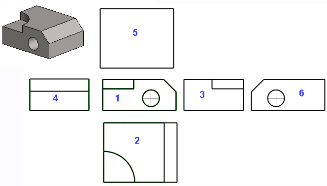
The image below displays the location of a drawing's projections in relation to each other when using the one-flip method (default). The projection line will be highlighted when the cursor is near the projection area. The projection line is not drawn on a printout.
The program names the drawing with the projection names: VIEW1, VIEW2 etc. The name of the projection features the name of the part/assembly from which the drawing was made as a prefix.
The projection names are presented in the Drawing-tree, if you double-click the drawing in the feature tree of the Part or Assembly.

Projections in a drawing:

-
You can add a projection in a model drawing – an isometric projection, for example. Move the cursor in the model drawing window and select the context-sensitive function Projection.
-
You can edit the projection settings. Select a projection from the drawing and the Properties function.