
Flattening Drawing
Sheet-Metal Design
When the sheet metal part is finished, create a flattening drawing from it.
Create a flattening drawing as follows:
- Open the sheet-metal part in the working window.
- If necessary, activate a certain configuration of a model, which you wish to create a new drawing.
-
From the tree, select
 Drawings and select the context-sensitive function New Drawing.
 - (OR) Double click Drawings in the tree.
- (OR) Double click
- Fill in the data in the New Drawing dialog box. Select
 flatten sheet.
 - Select OK.
- Select the properties of the Flattening Projection. Projection Settings
- Select OK.
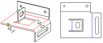
- Select the face based on which the flattening will be made. The program automatically suggests the largest planar surface as the flattening reference surface. Accept the selection by selecting the context-sensitive function
 OK or by pressing the middle mouse button or select a new planar surface.
 - Select the X direction of the flattening (edge line of a face). The program automatically suggests the longest edge line as the X-direction. Accept the selection by selecting the context-sensitive function OK or by pressing the middle mouse button or select a new edge line for the X-direction.
- Fill in the archives data of the drawing and select OK.
Note:
- If the corner of a sheet-metal part is closed, the corner opening will not be drawn in the flattened view of the drawing (default). If necessary, you can define trimming of the corners in the projection data.

Figure 2: The opening of a corner is not drawn. - You can edit projection data by selecting the projection and selecting the context-sensitive function
 Properties.
 - If you want to create a section of a flattening projection, remove the selection
 Draw Geometry Simply in the flattening projection properties.
 - A flattening projection includes the data of the library features added to the sheet face, including their insertion points. You can save the file in the DWG format, for example, for determining machining paths (CAM).
- You can also add a new flattening projection to an existing drawing. New Projection