
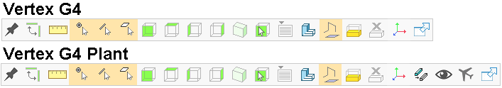
Tool Strip - Part / Assembly
The content of the tool strip is defined according to what kind of object is opened in the window.
- Open the tool strip by moving the cursor to the top edge of the working window.
- Select functions from the tool strip.
- Select snapping.
- Snap to Point
- Snap to Line
- Snap to Face
- Select also other parts when editing a part or a sub-assembly. For example, a function is selected: When you select by using a selection filter, only the parts in the current assembly and belonging to it are selected.
- Select Projection.
- Front
- Top
- Left
- Right
- Perpendicular
 Perpendicular
 - Isometric Isometric Projection
- Click from the model Click the projection from the model
- Other Views Other Views
- Select Draft.
- Wireframe Wireframe
- Shaded Shading
- Show reference geometry Visibility of the Assembly Auxiliary Geometry
- Set 3D limit / Delete 3D limit. Set / Delete 3D Limits
- Local coordinate system. Set a Local Coordinate System in a Model
- Remove markings.
 (Only Vertex G4 Plant)
 - Set view point.
 (Only Vertex G4 Plant)
 - Fly in the model.
 Fly in the model (Vertex G4 plant only)
 - Pin / Hide
 Toolstrip - Pin
- Wireframe