
Annotations
- Apply only to projection drawings made from 3D models stored in the archive
- Lines of drawings created with the Insert 3D View with Attributes to 3D Window function.
Free Annotation
- On the
 tab, in the Annotations group, select
  Free annotation.
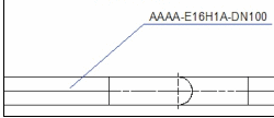
 - Add annotations to a drawing.
The ANNOTATION ALTERNATIVES dialog box is opened.
- Select the appearance of the annotation text: Select the tab One row, Many rows or Two parts.

- Select the annotation text in the menu field. For example, Pipe Position, Pipe Class, Additional Information. This process selects the attribute database fields of the part in the 3D model.
- Select OK.
For example:
Type-specific Annotation
Functions as free annotation, but you can determine the settings based on the part type. For instance, the annotation text for pipes can be defined to be different than that of valves.
- On the tab, in the Annotations group, select
 Type-specific annotation.
 - Select an element.
Type-specific Settings
- On the tab, in the Annotations group, select
 Type-specific annotation settings.
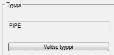
Determine the options. Click the Select Type button in the dialog box.
Annotate Reference Grid
When a 2D drawing is made from a model, the reference grid texts are shown as they are in the 3D model.
In a 2D drawing, the reference grid texts should be at the ends of the lines. This can be accomplished by using the Annotate Reference Grid function.
You can use the function for the projection lines of drawings created from 3D models saved in the archive.  Reference Grid
- On the tab, in the Annotations group, select
 Annotate reference grid.
 - Select the reference grid.
- In Flow, the 3D model must be in the working window in the editing mode.
Insert Flow Arrow Symbol
Used to indicate the flow direction in isometrics or PI schemas, for example.
- On the tab, in the Annotations group, click
 Insert flow-arrow symbol.
 - Enter the scaling factor for the flow arrow.
- Select the start point of the flow arrow.
- Indicate the flow direction.
- Select Confirm.
Add Frames to Part Numbers
You can use frame shapes to group or highlight part numbers.
- On the tab, in the Annotations group, select
 Add frame to partnumber.
 - Select the shape of the frame:
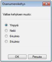
- Select OK.
- Indicate the part number. The frame changes.
For example, octagon and square.

Edit/Change Texts
You can change texts or parts of them in the following:
- Selected drawings
- Active drawings
Do as follows:
- On the tab, in the Annotations group, select
 Edit texts.
A dialog box is opened. Click the Help button. Change/edit the text as instructed.
PI Schema Data Annotation
- Add annotations to a drawing. The program finds the parent element selected in a 3D model from the drawing and adds the PI position’s selected data linked to the parent element as an annotation text to the drawing.
- On the tab, in the Annotations group, select PI-schema data annotation.