
Static Collision Detection - Plant
Piping Design
Align the collision detection to the assembly model or a pipeline selected from the assembly.
- Start the video help by clicking Shift + left mouse button on the button.
Finding Collisions in the Assembly
Find collisions in the assembly or limit the search to a particular line position.
- On the
 tab, in the Collisions group, select
  Find All Collisions.
 - Define the settings for the collision detection. Select either of the following:
- Find All Collisions - Finds all collisions in the model.
- Find Collisions of Pipe Components Only - Only finds collisions between pipe components.
- Limit the collision detection to a certain line position.
 Find collisions of line position - Limit the search to a certain line position. Click the Point from model button and select the pipe part belonging to the line position from the model. All parts in the pipeline are selected and the collisions are indicated.
- Select OK.
Vertex finds the collisions in the model. The collision detection of a larger model takes more time.
- When the collision detection is finished, a dialog box opens for viewing the collisions.

- To browse the data arranged into to rows, press Shift + Down Arrow.
- The dialog box buttons function in the same way as with the Isometrics function. For example, Limits++, Limits OFF etc.
- The Add Ball button indicates the collision points in the model. Select either of the following:
- Only to This Collision - Adds a ball, whose information is shown in the dialog box, to the collision.
- To All Collisions - Adds a ball to all collision points found.
- Select OK.
Collision Point Indication
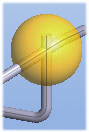
Collision points are indicated in the assembly model with colored balls: red, yellow and green.
- In the model if the Add Ball function is used.

The collision volume determines the ball color:
Red - Largest collision volume.
Yellow - Medium
Green - Smallest
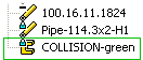
- In the assembly tree, collisions are indicated with the name COLLISION. The color suffix (red, yellow, green) signifies the collision volume.
Viewing the Collision Point
Zoom to the collision point.
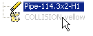
- Select the collision from the assembly tree. For example,
 COLLISION-yellow.
 - Select the context-sensitive function Other Functions> Zoom.
View the collision.
- Double-click the collision ball.
The colliding elements are highlighted in the assembly tree and the model. Hide the collision ball.
The item
COLLISION-yellow is created in the model's collision point. This is highlighted in red.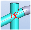
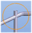
- If you select a hidden collision point in the assembly tree, the point is circled in the model.
- Do either of the following:
- Exit by pressing the Esc key.
- Create a new part of the collision part by pressing V.
- You can restore hidden collision balls via the assembly tree. Select the collision in the assembly tree and select the context-sensitive function Restore> Restore.
- Select
Removing a Collision Ball
- Do either of the following.
- Select a collision ball in the assembly model.
- Select the collision in the assembly tree.
- Select the context-sensitive function Delete.