Vertex BD 2021 (27.0) - What's New
Familiarize yourself with the new features.
WORKING IN THE DRAWING AND MODEL WINDOWS
New Graphics Engine
Until now, Vertex CAD programs have used the OpenGL programming interface to present 3D graphics. As the model sizes grow, their slow handling and rotating has become a problem. In this version, OpenGL technology has been abandoned and the drawing of 3D graphics has been completely rebuilt. The drawing now uses the Microsoft DirectX programming interface. The handling and rotation of large models is considerably faster than before.
There are no longer any special requirements for the graphics card and no separate CAD graphics card is required, but you can use an integrated Intel or AMD graphics card, for example.
However, a more powerful graphics card will improve the performance of Vertex CAD, as the new graphics engine will be able to take better advantage of the graphics processor's performance.
As part of the reform, the graphics settings have changed. New settings have been added and some redundant settings have been removed.
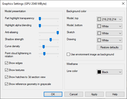
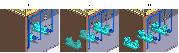
- Highlight alpha blending
Adjustment of the visibility of the selected object and the geometry in front of it. With a value of 0, the geometry in front covers the selected object. With a value of 100, the selected object covers the geometry in front of it. With other values, the selected object is partially visible through the geometry in front. In the example figure, the transparency of the selected part is set to 0.
- Shadow strength
Defines the darkness of shadows (0-5). When the value is 0, shadows are not drawn at all.
- Curve density
Defines how accurately curves (circles, splines, etc.) are drawn in sketching, and the control curve in part and assembly models in the Vertex G4 application. In the Vertex BD application, the setting can affect the performance of models with a lot of curved profile features(steel framing environments).
- Use environment image as background
Select the environment image added in the model as the background for the model or sketch. This requires, that the Rendering add-on feature is available.
- Wireframe: Line color
Select the color by which the lines are drawn in the model's wireframe presentation. With Default, the lines match the colors of the materials.
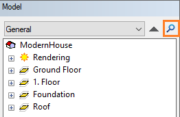
Find From Object Tree
Search for objects by using the search function  Find from Object Tree in the object tree.
Type the character string that appears in the object name in the text box of the dialog box.
- Whole word - Find the object whose full name is the given string.
- Case sensitive - Find the object in the name of which the uppercase and lowercase letters match the given string.
Search for objects by clicking OK.
Objects that meet the search criteria will be selected in the object tree and in the drawing/model.
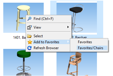
Add the document directly to the Favorites folder you want in your browser
If you have added your own folders in your browser favorites, you can add the selected document directly to the desired folder. Previously, the document was always added to the Favorites folder, and after that, you were able to move it to the desired sub folder by using the drag and drop method.
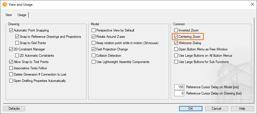
Centering Zoom
By default, rotating the mouse wheel moves the area where the cursor is to the center of the working window. If you want to zoom without centering the drawing/model, turn off the Centering Zoom setting.
Select  >
>  Preferences >
  Drawings, Models, and the tab Usage.
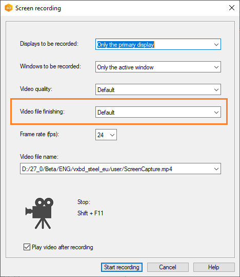
Video file finishing
When you create a video of using Vertex program, you can choose the level of encoding for the finishing of the video file. When more time is used in finishing the video, the resulting video will require less storage capacity. The finishing does not affect performance or storage use while recording, but only the end result of the created video.
- Finishing a long video takes more time than finishing a short one, but the waiting time can be shortened by speeding up the finishing. In this case, the final video file is larger.
- The file size of a long video is larger than that of a short one, and for example, the size limit of an e-mail attachment may be reached. You can reduce the file size by slowing down the finishing.
PROJECTS
Project Settings
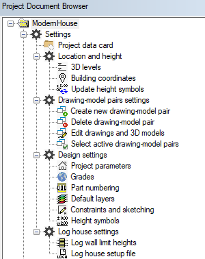
The project settings were previously placed in the right-click menu in the document browser. The settings have been regrouped and can be found directly in the  Settings branch of the document browser. To open the settings, double-click the title.
Building Coordinates and Heights
Select Active Drawing-Model Pairs
Project-specific Grade Settings
Project-specific Layer Settings
Parametric Building Model - Settings
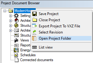
Open the Project Folder
The function was previously placed in the project settings. It can now be found in the menu that opens by right-clicking the project ID.
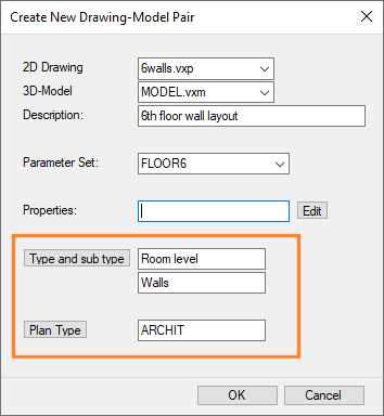
Drawing-model Pair Properties
- Copying objects - When you copy objects from one floor to another, or from one project to another via the clipboard, the program tries to position the objects in the correct drawing-model pairs. The functionality has already been in previous versions, but with the new drawing-model pair properties, knowledge about the correct drawing-model pair is better managed.
- Managing materials - The materials of the objects in the sub project’s drawing-model pair are collected on the right floor in the main project. For example, you can add the sub project’s drawing-model pair “1st floor walls” to the main project’s drawing-model pair “2nd floor walls”. When you collect the materials, the walls of the sub project are marked as belonging to the second floor.
Set the properties when you add a new drawing-model pair to a project.
When you open an old project whose drawing-model pairs do not have a type, sub type and plan type, the program automatically sets them according to the names of the parameter sets in the project’s PARAMETERS file and the drawing and model file names of the drawing-model pairs.
Project-specific Layer Settings
The feature has already been introduced in the 2020 (26.0.03) version.
You can select to use project-specific layer settings instead of the default layer scheme. The settings are saved in a project-specific component library. You can disable the project-specific settings by re-enabling the default layers of the system. In this case, the component library folder is deleted from the project folder.
- Open the project's document browser.
- Open
 Settings > Design settings.
 - Double-click
 Default layers.
 - Do either of the following:
- Use system layers as default - The project-specific layer settings are disabled, and the component library folder complibs/vxlayer-schemes_proj is deleted from the project folder.
- Use project-specific layers as default - Set the desired layers by clicking Edit project-specific layers. Edit the layers in the same way as the layers in the default layer scheme. The settings are saved in the project-specific component library complibs/vxlayer_schemes-proj folder.
- Select Update layers in existing drawings to load the selected default layer scheme (system layers or project-specific layers) into all project’s drawings. The layer names, visibility and layer groups are updated to the project’s drawings.
- Confirm the updating of the project's drawings by clicking Yes.
Project-specific Layer Settings
ARCHITECTURAL DESIGN
New Components to Component Libraries
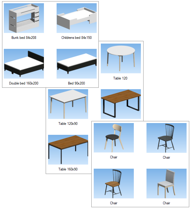
New components have been added to the component libraries and old components have been redesigned. For example, the furniture selection includes new beds, chairs, tables and table groups.
Furniture Color Fill to Its Own Layer
The 2D presentations of the furniture have been modified so that their color fill goes to the layer "149 Furniture Color Fill". The layer 149 has been added to the default layer scheme. The lines of the furniture go to the layer “36 Furniture” as before. For fixture, the corresponding layers are "59 Component color fill" for color fill, and for example "75 Appliances" or "76 Cabinets & Vanities" for lines, depending on the component type. Once the geometry of the furniture and fixture is separated into their own layers, you can change their visibility in the floor plan by changing the visibility of the layers.
In old projects, the geometry of furniture needs to be updated, and the default layer scheme needs to be restored to the project's drawings, when the default layer scheme of the software supplier is used. If a customized default layer scheme is used (in custom/setup/layer_templates), add the layer 149 to your layer scheme and restore the default layer scheme to project's drawings.
Restore Default Layer Scheme for the Entire Project
The 2D presentations of furniture components have also been simplified, for example, the double lines of cabinets have been changed to a single line.
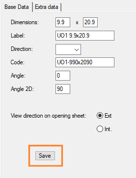
New Size to the Door Library
You can add new sizes to the standard door library of the software supplier in the same way as new window sizes to the window library. Edit the dimensions of a door in the library and save the new size to the door library by clicking Save.
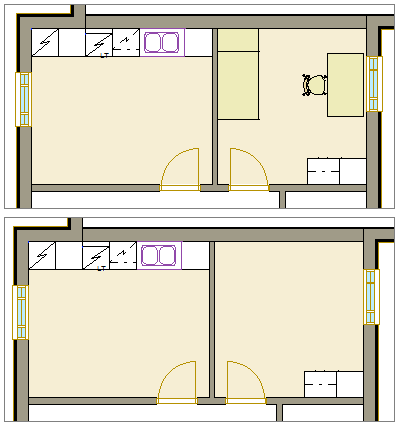
Dormer
- You can select a different wall type for the front wall and side wall of the dormer already when adding the dormer.
- You can clip the top of the walls to the roof of the dormer or to a given height.
- You can select the height level of the main roof or a given floor level as the starting level for the bottom of the walls.
- You can add 1-3 windows to the front wall. When you add three windows, you can select different windows at the sides and in the middle.
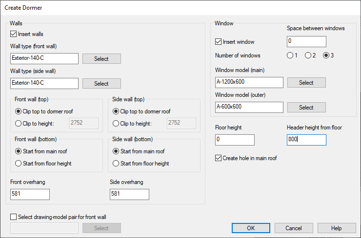
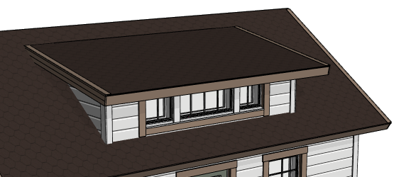
The program now better takes into account the nearby or connected eaves when adding eaves trims to the dormer roof.
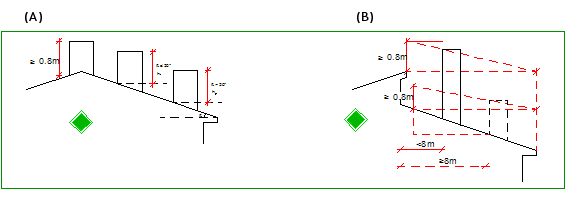
Set the Chimney Height
The feature has already been introduced in the 2020 (26.0.04) version.
The calculation of chimney height has been updated to comply with the last Finnish building regulations (regulation 745/2017).
Detail Symbol with a Reference Line
When you add a detail as a symbol to the floor plan drawing, you can select the property Reference line for the symbol. Click the start point of the reference line and the location of the symbol. You can move the start point of the reference line or the symbol itself from grip points.
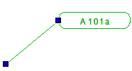
Before clicking the location of the symbol, you can select the auxiliary function Set reference point from the right-click menu, and select the desired point from the symbol as the locating point.
The drawing properties of the reference line are defined in the system settings. The name of the line is DETAIL.REFLINE.
Edit the Section Depth from the Grip Point
The feature is available from version 27.0.02.
You can edit the depth of a building cross section by moving the arrow grip point in the floor plan drawing. All objects from the generation model that are between the section line and cutting depth are included in the section. With a section depth of 0, all objects that are in the direction of the section from the section line, are included.
- Select the section symbol in the floor plan drawing.
- Click the arrow grip point.
- Section depth is 0:
- Section depth is unequal to 0:
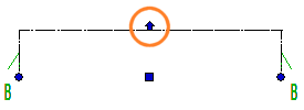
- Section depth is 0:
- Click the new location.
Edit the Section Depth from the Grip Point
Line Font of Wall, Floor and Roof Layers in a Section View
The feature is available from version 27.0.02.
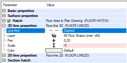
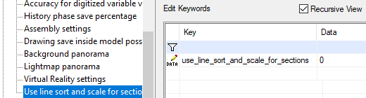
By default, the line font of layers in a section view is a continuous line. If you have selected another line font for a layer in the structure properties with the 3D line parameter, you can specify this line type to be used in the section view. The line font to be used is defined in the system settings in the 3d keyword group with the keyword use_line_sort_and_scale_for_sections.
| use_line_sort_and_scale_for_sections = 0 | The line font is a continuous line. |
| use_line_sort_and_scale_for_sections = 1 | The line font and scale are read from the structure properties from the layer parameter 3D line. |
Drawing Properties in a Section View
STRUCTURAL DESIGN
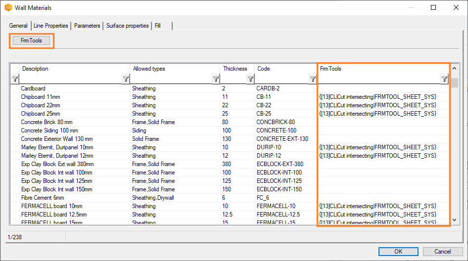
Default Framing Tool of a Wall, Floor or Roof Layer
In layer libraries, it is now possible to set a default framing tool for a layer in a wall, floor or roof. When you change the layer material, the default tool set in the layer library is also changed to the framing tool of the layer. Previously, the framing tool had to be changed separately after changing the layer material.
- If the current layer does not have a framing tool, and a new material is selected for the layer.
- If the layer is of a different type than the original, and a default tool has been set for the layer in the layer library.
If you change the layer to a layer of the same type but different material, and you have set a framing tool for the layer, you will be prompted:
- Load framing tool from library (current tool will be overwritten)?
It is possible that you have changed the parameters of the framing tool and want to keep the changes when the layer material is changed. You can choose to load the default tool set in the layer library or keep the existing one.
The default framing tools have been preset in the layer libraries included in the standard software delivery. The custom update function adds the required field (FRMTOOL) to the customer-specific layer library databases located in the custom/complibs folder. Open the libraries for editing and set the desired default framing tools for the layers.
Set the Default Framing Tool for a Layer
Default Presentation Method of Profiles in the Model
In the wood framing environments, the default presentation method of profiles in the model is now True Features. The features added to profiles appear realistic, such as the holes in the service hole lines. Previously, this presentation method was selected by editing the profile properties.
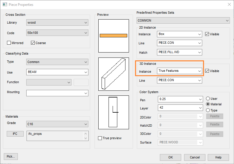
In the steel framing environments, the default presentation method of profiles is unchanged (Holes as Lines). Thanks to the new 3D graphics engine, performance is very good even in the steel framing environments, but due to the large amount of machinings, the creation and updating of the geometry is slower when the 3D presentation is True Features.
Notching Tools in the Detail Connection Browser
You can notch a part with a machining G4 part. Previously, the notching part was added by using the function  G4 Part from File. The machining parts have now been saved in the joint library (macro_notch) included in the standard software delivery. Select the part from the folder Notch / Notching tools in the connection detail browser.
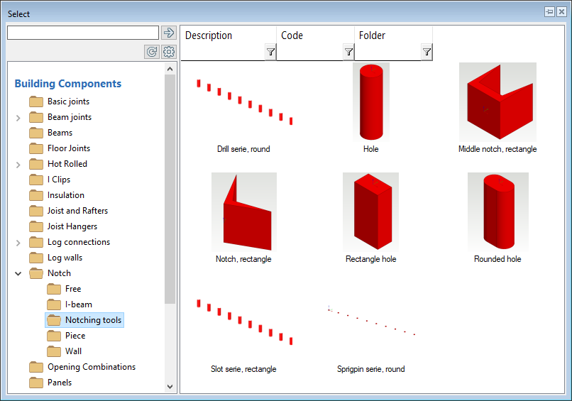
So far, creating your own machining parts is not possible.
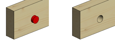
To notch all the parts that the machining part or parts hit at once, proceed as follows:
- Select one or more machining parts. You can select all machining parts at once when you select one and then press Ctrl+A.
- Right-click to open the context-sensitive menu, and select Advanced > Modify All Parts with Selected. All the parts that are hit by the machining part or parts are notched.
Notch a Part With a Machining Part
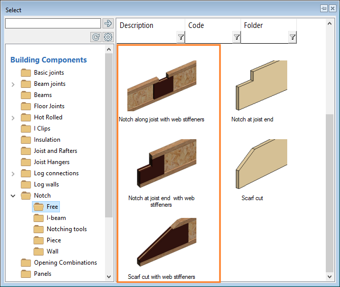
Beam Notches with Web Stiffeners
Notches with web stiffeners for I-beams have been added to the connection detail browser.
Select the folder Notch / Free in the connection detail browser.
Notching Along Joist Length With Web Stiffeners
Notching a Beam End With Web Stiffeners
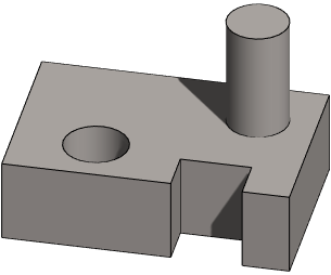
Grip Points of Punch Components
The feature has already been introduced in the 2020 (26.0.03) version.
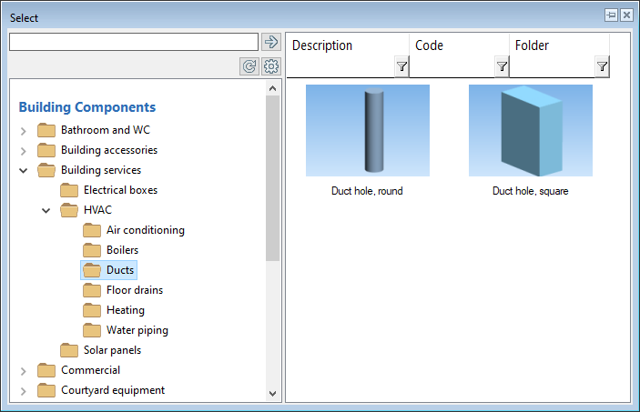
You can add a punch component to a panel that punches the sheathing, insulation, and cladding layers of the panel. The punch components can be found from the folder Building services / HVAC / Ducts in the component browser.
You can change the size of punch components by using the grip points.
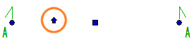
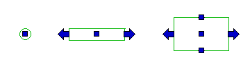
In the 2D presentation of the component, the grip points are at the edges that can be stretched in the drawing. The longitudinal grip point is an arrow and in other directions the grip point is a square. The square grip point in the middle of the component is for moving the component.
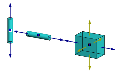
In the model, the longitudinal grip point is blue, the others are yellow. For a cylinder, only longitudinal stretching is possible. You can change the diameter by editing the cylinder parameters.
Wall Panel Backer at an Opening
The feature has already been introduced in the 2020 (26.0.07) version.
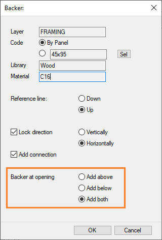
Once you have generated the wall panels and added parts to them, you can add a backer to the panel by using the function in the framing accessories browser. You can define whether the the backer comes below or above the opening, or on both sides.
- Select Modeling | Panel |
 Wall >
  Framing Accessories.
 - Select the folder Studs.
- Double-click the thumbnail image (0010) Backer.
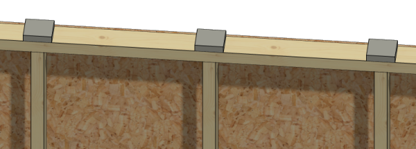
Vibration and Sound Insulators to Top Plate
You can add a piece of isolator to the stud location in a wall panel by using the function in the framing accessories browser. The isolator is added on the top plate at the location of the stud. The program adds the isolators automatically at the location of each stud in the selected wall panel.
- Select Modeling | Panel | Wall > Framing Accessories.
- Select the folder Vibration isolations.
- Double-click the thumbnail image Damper.
Framing Accessories - Vibration Isolators
Evenly Spaced Trusses
The feature has already been introduced in the 2020 (26.0.07) version.
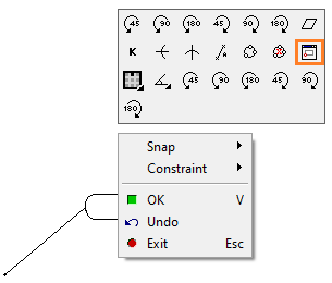
When adding a truss area, you can select an auxiliary function for dividing trusses evenly in the truss area so that the distance between them is at most the interval defined in the parameters. You can select the auxiliary function from the right-click menu before selecting the truss line points.
Add a Truss Area and Truss Volumes
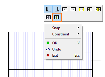
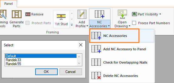
Possibility to Define Several Machining Lines
The feature is available from version 27.0.02.
Customer-specific machinings are defined in a setup file in the ../custom/setup folder. There can be several setup files. The default file is called CncAccessories.Setup. Other files should be named as follows:
CncAccessories(DESCR).Setup.
DESCR is a name describing the machining line. For example:
CncAccessories(Randek33).Setup
CncAccessories(Randek55).Setup
When adding a machining line, the program asks you to select the file to be used. The option Default is the CncAccessories.Setup file.
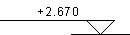
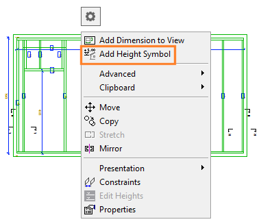
Height Symbols to Wall Panel Drawing
You can add a height symbol to a wall panel drawing in the same way as to elevation or section drawings of a building. A height symbol in a wall panel drawing may look like this, for example:
- Set the height data of the building.
- Select the height system (relative or absolute) for height symbols.
If you change the height data or height system of the project, the program suggests updating the drawings and you can select the drawings to be updated.
Height Symbol to Wall Panel Drawing
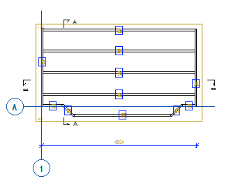
Grid to a Panel Drawing View
You can show a grid in a panel drawing view. In a wall panel drawing view, only the grid lines perpendicular to the panel are shown. You can move the grid line label and edit the label properties in the view.
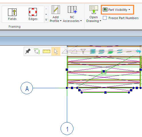
First, set the grid visible in the panel drawing as an external part by using the function Part Visibility.
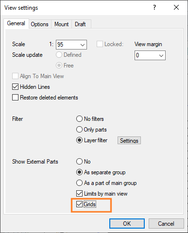
For the panel drawing view, select the property Show External Parts: Grids.
External Objects to Panel Drawing
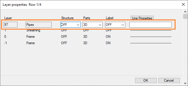
Pipes to a Panel Drawing View
You can also connect pipes to a panel as external objects. To do this, there is a new function Attach Pipes.
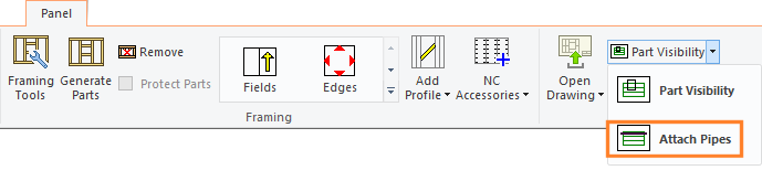
The pipes are connected to the panel as a separate layer. The sequence number of the layer is 97. You can show the pipes in the panel drawing view when you select the 3D presentation method for the layer parts in the view properties.
You can also show or hide the labels.
You can also add a schedule of the pipe parts to the panel drawing. Add a view to the panel drawing, select the view type Schedule, and select the desired option from the list.
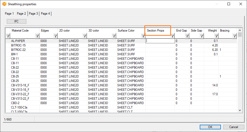
Section Hatch for a Sheet Layer in a Panel Drawing
In the sheathing library, it is possible to assign a section hatch to a sheet that appears in the section views of a panel drawing. The custom update function adds the field SECTPROP into the customer-specific sheathing database custom/dbases/d_SHEETLIB.
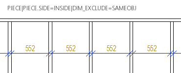
Additional Parameters for Dimension Lines in Panel Drawings
- Dimension between parts
The feature has already been introduced in the 2020 (26.0.09) version.
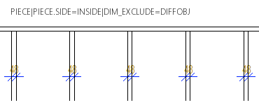
You can dimension the distance between the studs or joists or the insulation between them by setting the additional parameter DIM_EXCLUDE for the dimension line. When the additional parameter is used, part of the dimension line points are filtered out.
For example, the dimension line parameters:- DIM_EXCLUDE= SAMEOBJ - Adjacent dimension points related to the same part are filtered out.
- DIM_EXCLUDE= DIFFOBJ - Adjacent dimension points related to different parts are filtered out.
-
Diagonal dimension of gable panel
The feature has already been introduced in the 2020 (26.0.04) version.
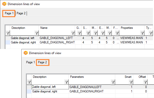
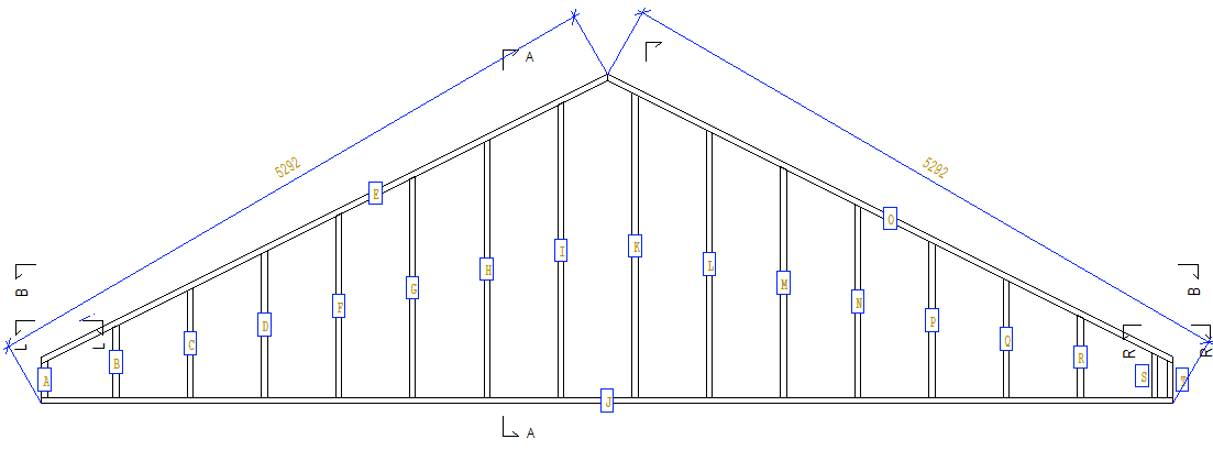
In the dimension line library, you can define a diagonal dimension line for a gable panel from the bottom of the panel to the highest point of the ridge. Set the following additional parameters for the dimension line:- GABLE_DIAGONAL|LEFT
- GABLE_DIAGONAL|RIGHT
For example:
- Reference surface of a cladding board
The feature has already been introduced in the 2020 (26.0.07) version.
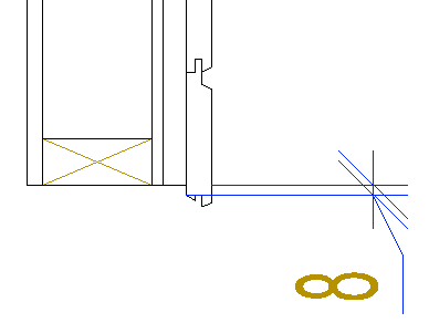
You can define the reference surface of a cladding board to be used in dimensioning by using an additional parameter SID~REFSURF for the dimension line.- When you want to dimension according to the back edge of the profile, the additional parameter is SID~REFSURF=BOT.
- When you want to dimension according to the front edge of the profile, the additional parameter is SID~REFSURF=TOP.
If the reference surface is not determined, the outermost dimensions of the profile are used in the dimensioning.
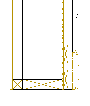
In the example figure, the siding offset has been dimensioned with respect to the frame. The additional parameter SID~REFSURF=BOT has been used, i.e. the offset is dimensioned according to the back edge of the cladding board.
Dimension Lines in a Panel Drawing
Line Font of a Loose or Manual Part in the Section View of a Panel Drawing
The feature is available from version 27.0.02.
| use_line_sort_and_scale_for_sections = 0 | The line font is a continuous line. |
| use_line_sort_and_scale_for_sections = 1 | The line font and scale selected in the view properties are used. |
Previously, the line font was always a continuous line.
Define an Exceptional Mounting Method for a Part
Automatic Panel Stacking
The automatic panel stacking function collects the panels from the entire building, or only from the open drawing-model pair, and creates the panel stacks automatically. The ability to select panels from which stacks are created automatically has been added to the function. Other panels retain the previously set stack data. For example, you can manually create stack diagrams for some panels (for example, when you want to place the panels in a specific order in a stack), and then use the automatic function for other panels that you select from the list.
Sort Panel Drawings by Stack When Printing
Panel stack data can be used to sort panels by stacks when panel drawings are printed.
The stack label is displayed in the Additional data field in the Document schedule dialog box, when you select the panel drawings in the project document browser and the context-sensitive function List view. You can sort the panel drawings by stack by clicking the field title.
Panel stack data can also be used to sort panels when a PDF set is printed of the panel drawings. You will need a software customization to be able to use this feature.
Sort Panel Drawings by Stack When Printing
2D DRAWING
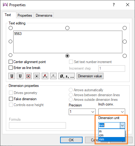
Unit of Dimensions
You can change the dimension unit in the dimension properties. This feature can be useful in site plans, for example. You can change the unit to a centimeter or a meter instead of a millimeter.
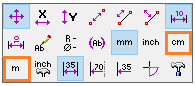
When adding a dimension, you can change the unit from the right-click menu:
Afterwards, you can change the unit in the dimension properties:
SUB PROJECTS
Sub project functions are included in the Townhouse Design add-on feature of the Vertex BD software.
Contextual Tab
You can select sub project functions from the contextual tab. First, select a sub project to activate the tab.
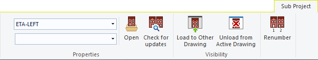
Open a Sub Project for Editing
Unload a Sub Project From an Active Drawing
Up-to-dateness of Sub Projects
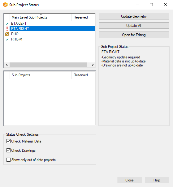
When you open the main project, the sub projects are opened in the state they were in when you last saved the main project. At opening, the program checks whether the geometry of the sub project, materials collected to the components.xml file, panel drawings or part drawings are up-to-date, and you can choose what information you want to update.
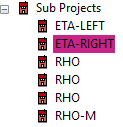
If the sub project is not up-to-date, it is highlighted in a different color in the object tree.
The up-to-dateness of sub projects is also checked when you create a material report of the main project to an Excel file.
You can check the up-to-dateness of a certain sub project by using the function  Check for Updates on the contextual tab even when the main project is open.
Symbols describing the status of the sub project:
 - The sub project is up-to-date.
 - The geometry of the sub project is out of date.
 - The material data (components.xml) of the sub project is out of date or the sub project is mirrored.
Sub Project Documents in Main Project Document Browser
You can open and print the sub project’s panel drawings and part drawings of panels from the project document browser in the main project.
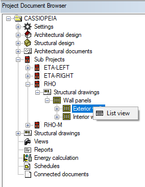
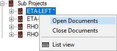
- The panel drawings and the part drawings of the sub project are displayed in the project's document browser. If the panel drawings have changed and they have been updated during the up-to-dateness check, the drawings still need to be updated in the project document browser. The subproject ID is marked with an asterisk in the project document browser. Select the ID of the project, right-click and select Open Documents from the menu.
- Part drawings are updated in connection with the up-to-dateness check when rule-based part numbering is used. If default numbering is used, and the part drawings are out of date, the sub project must be opened and the part drawings updated separately. See Part Numbering.
Sub Project Documents in Main Project Document Browser
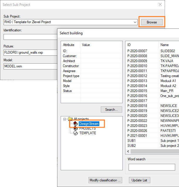
Add a Sub Project from the DesignStream System
The feature has already been introduced in the 2020 (26.0.07) version.
Previously, a project exported to the DesignStream system could not be directly added as a sub project, but had to be opened in the local project archive first. This is no longer necessary, and you can select a sub project to be added from the DesignStream system in the same way as from the local archive.
Sub Project Materials to Excel Report
When you create a material report of the main project to an Excel file, the materials are collected from the entire project hierarchy. The standard software delivery includes example report templates, in which sub project information such as listings of panel parts are presented in their own sheets.
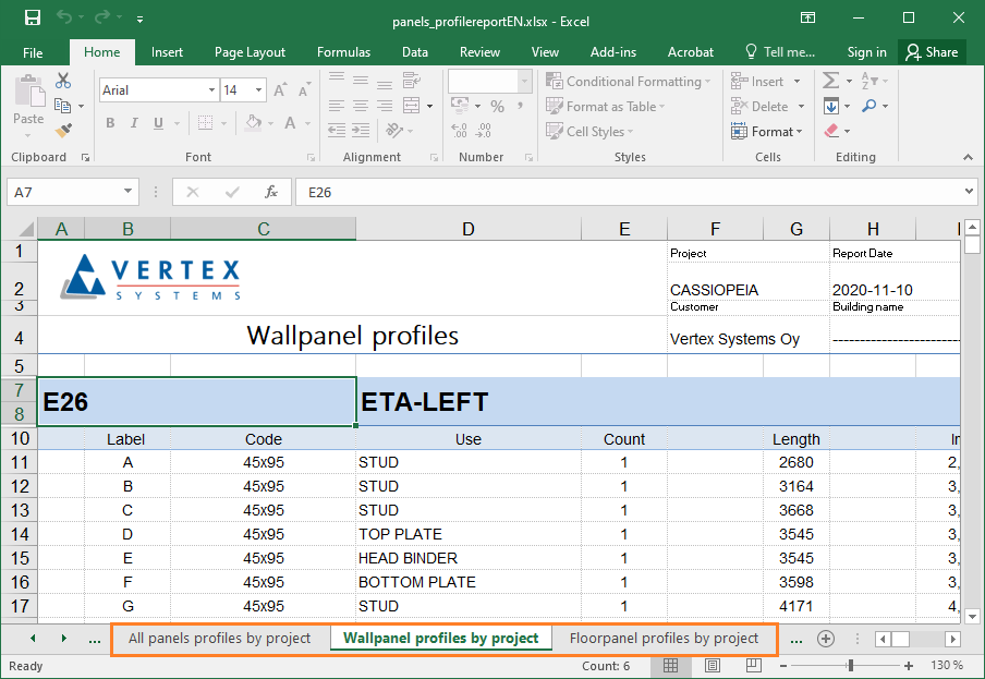
Material Report to an Excel File
Panel Parts Belonging to a Module
A panel part always belongs to the module to which the highest hierarchy level of the panel belongs. This also applies to a beam or column that is part of a beam panel, frame line or panel assembly. A beam or column belongs to the module to which the highest hierarchy level of the panel belongs, regardless of which module area the beam or column is located in.
Edit the Building Components of a Module
Module Name or Apartment Label in Panel Label
- #MOD# - Module name
- #APT# - Apartment label
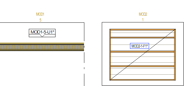
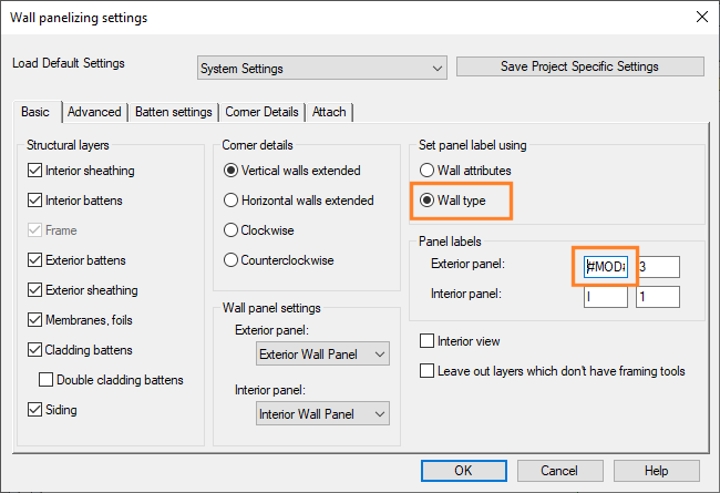
For a wall panel, the additional attribute is set in the framing tool of the main frame. In this case, you must select the panel label to determined by Wall attributes in the Wall Panelizing Settings dialog box. For example:
#MOD#-U
or
#MOD#-#APT#-U
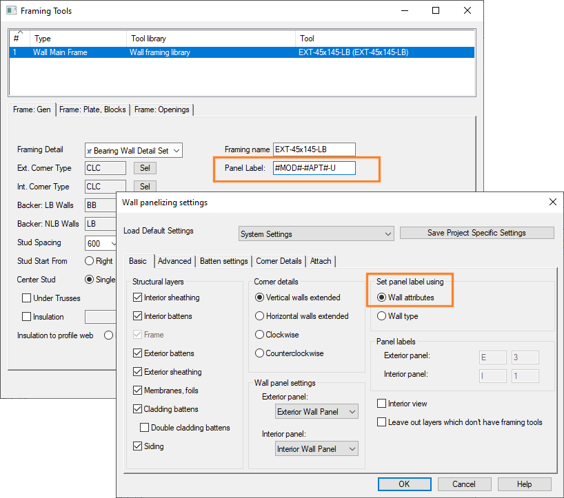
Alternatively, you can select the panel label to be determined by Wall type, and enter the additional attribute in the panel label field.
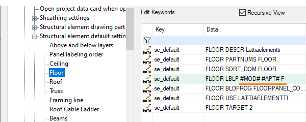
For floor and roof panels, the additional attribute of the label is set in the system settings, in the bdsxx / Structural element default settings keyword group. For example, for floor panels:
se_default= FLOOR LBLP #MOD#-F
or
se_default= FLOOR LBLP #MOD#-#APT#-F
However, use is not generally recommended. It restricts the use of a panel in cases where multiple modules may have a similar panel, for example.
Module Name or Apartment Label in Panel Label
Only Parts Belonging to the Module are Shown in the Module Drawing
The feature has already been introduced in the 2020 (26.0.03) version.
A module drawing contains only those parts that belong to the module. A building component belongs to a module if its center point is inside the module line, or exactly on the module line. However, the module line is used to delimit the basic geometry and sub projects if they are within the module limits.
PUBLISHER
Publisher is an add-on feature of the Vertex BD software.
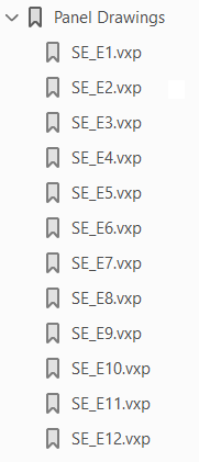
Order of Documents in a PDF Book
You can publish multiple documents as a single PDF file, a so called PDF book. For example, you can publish all panel drawings as a single PDF book. The documents are arranged in the PDF file in the same way as in the project document browser. The order takes into account the alphabet and numbers.
IFC LINK
IFC Link is an add-on feature of the Vertex BD software.
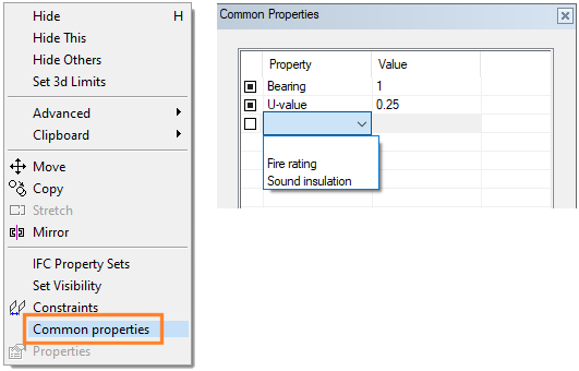
Common Properties
- Bearing
- U-value
- Fire rating
- Sound insulation
- For walls, bearing and U-value appear in wall properties.
- For windows and doors, fire rating and sound insulation appear in accessory data.
For other building components, you can add common properties as follows:
- Select the building components.
- Right-click to open the context-sensitive menu.
- Select Common Properties.
 - All the selected building components have the property in question and it has the same value.
 - Some of the selected building components have the property in question or the components have different property value. If you do not change the selection, the building components will retain their different values. If you select the check box, all the selected building components will be affected by the change.
Project Information to IFC File
Project information related to the site, building, people, and organization is written to the IFC file. Information is needed in utilizing the information model in the building permit process, for example.
If necessary, edit the project information to be written to the IFC file by clicking Project Info in the IFC Export dialog box. This function opens a dialog box with fields on the left showing the information to be written to the IFC file. The fields on the right show the information to be read from the project archive. When you open the dialog box for the first time, the contents of the fields are the same on both the left and right. You can edit the contents of the fields to be written to the IFC file. Fields with different contents in the IFC project information than in the project archive are highlighted in a different color. You may have edited the IFC project information, or the project information has changed in the project archive.
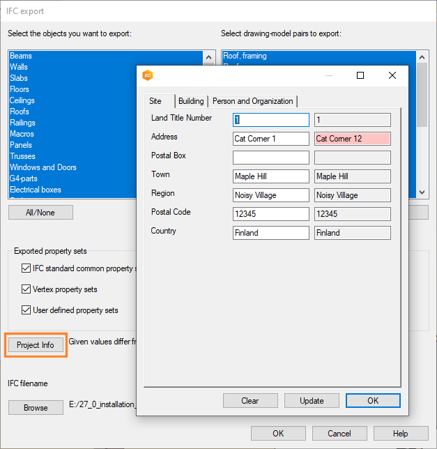
- Update - Update the IFC project information to match the information in the project archive.
- Clear - Clear all the IFC project information fields.
Accuracy of Geographical Coordinates
Accuracy has been increased to millionths of a second by six digits. Previously, accuracy had been presented with three digits. This new accuracy is practically required when it is necessary to plant a house model, for example, in a city model with sufficient precision.
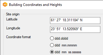
The ETRS-TM35FIN coordinate format option has been removed as redundant. IFC export always uses the WGS84 system according to the standard.
Building Coordinates and Heights
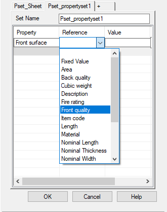
Quality Information of CLT sheets to IFC file
- Front quality
- Back quality
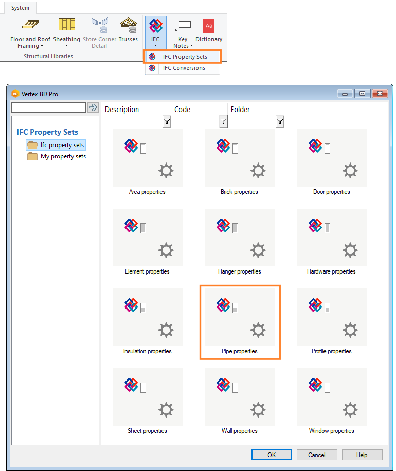
IFC Property Set for Pipe Parts
The IFC property sets library now also has a default property set for pipe parts. This IFC property set, or a copy of it in the customer-specific property set library, is always set by default for new pipe parts added to the model. You can edit the IFC property set of a pipe part added to the model by using the context-sensitive menu function IFC Property Sets.
Edit the Vertex Property Sets of an Object
Edit the Vertex Property Set Library
File Already Exists
When you save a model to an IFC file, you receive a warning if the file already exists with the same name. If necessary, you can enter a new file name.
2D Presentation of Objects when Importing an IFC Model
When you import an IFC model as an object model, you can choose whether to create the 2D presentation of the objects in the floor plan. Previously, the 2D presentation was selected by default for some object types. The 2D presentation can slow down the import of a model considerably, so now the 2D presentation is not selected by default for any object type.
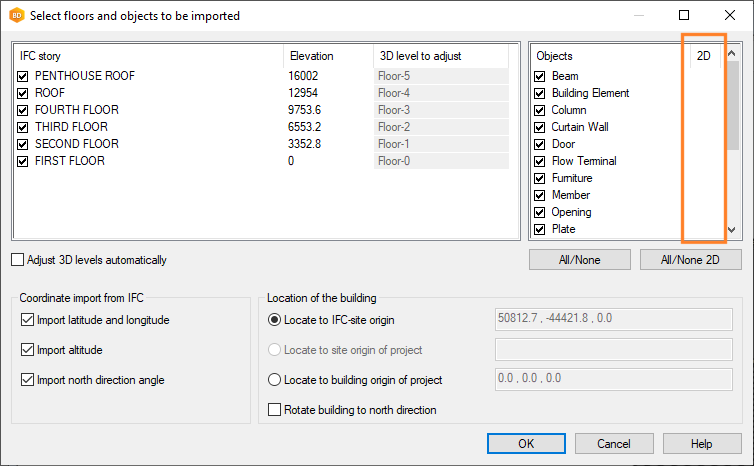
- Select an object.
- Right-click to open the context-sensitive menu.
- Select Presentation > 2D and 3D.
Import an IFC Model As an Object Model
PIPING DESIGN
Piping Design is an add-on feature of the Vertex BD software.
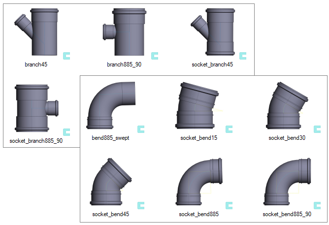
Pipe Components
The pipe components used in piping design have been redesigned.
CONTROLLING PRODUCTION LINE
Controlling Production Line is an add-on feature of the Vertex BD software. Each production line type requires a separate add-on feature.
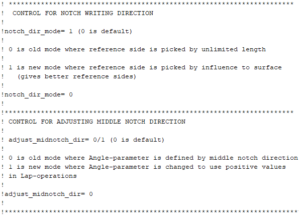
Defining the Reference Side in the Hundegger SC Setup File
The feature has already been introduced in the 2020 (26.0.08) version.
In the setup file, you can define which side is to be used as the reference side when writing machinings to the Hundegger SC file (*.bvx).