
Vertex BD 2022 (28.0) - What's New
Familiarize yourself with the new features.
LIBRARY REFORM
New Interface for Managing Libraries
This update is visible to the system administrator.
In previous versions, it was possible for users to create their own component libraries either by copying the system library folder to the custom/complibs folder in Windows Explorer, or by opening the library for editing using the old interface, creating a library with the same name as in the system side.
With the new interface, the system library remains unchanged and no copy to the custom folder is created.
The goal of the reform is to make it easier to manage the standard delivery and customization of the software when switching to the new main version of the program. The new interface makes it easy to distinguish between system libraries and your own libraries. In addition, libraries are grouped into subfolders by type.
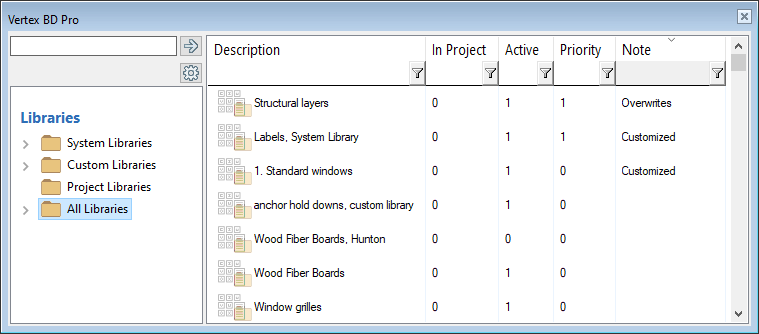
Open the Library Browser
Open the library browser by selecting System | Libraries |  Libraries.
- System Libraries - System’s standard libraries. You can copy components from a system library to your custom library.
- Custom Libraries - Customer-specific libraries. You can create new libraries and add components to them.
- Project Libraries - The project-specific library can be a log wall machining library, a template drawing library of panel drawings, or an IFC conversion rule library. You will identify the project-specific library from entry 1 in the Project column.
- All Libraries - All libraries combined in the same main folder.
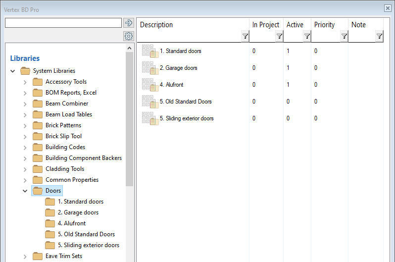
Sort Libraries by Browser Column
After selecting a main folder or a subfolder of a specific type, you can sort your libraries in the right browser pane by clicking the column heading.
- Description - Description of a library. You can search for libraries in the browser search box using the description.
- In Project - Project-specific libraries have the value 1 in the column.
- Active - When the value is 1 in the column, the library is enabled. With a value of 0, the library is deactivated.
- Priority - The number in the column defines the order of the libraries in the library list.
- Note - The column can have one of the following labels:
- Configured - Standard library label. Library components have not been copied to a customer-specific library, but a single parameter for one or more components has been modified. For now, this is only possible for some libraries, for example sheet and insulation libraries. In the browser, the label [Configured] is displayed in the library description. Only the configuration data is stored in the customer-specific folder in an xml file. You can deactivate/activate individual sheets or edit the following properties:
- Item
- Default
- Weight/Area
- Surface Color
- Bracing
- Additional parameters
- IFC Property Set
- Customized - Standard library label. The library has been modified with Vertex BD 2021 (27.0) or earlier, resulting in a customer-specific copy of the system library folder in the custom/complibs folder. The library folder contains individual drawing or model files or ADT programs that overwrite the corresponding standard library files. However, the library database is in the system library folder. You can view the modifications by selecting the library and Manage Modifications from the right-click menu.
- Overwrites - Custom library label. The library has been modified with Vertex BD 2021 (27.0) or earlier, resulting in a customer-specific copy of the system library folder in the custom/complibs folder. The library folder contains both component drawing or model files or ADT programs and the library database that manages the library. The customer-specific library overwrites the system library. You can view the modifications by selecting the library and Manage Modifications from the right-click menu.
- Restored - Standard library label. Customer-specific changes made with Vertex BD 2021 (27.0) or earlier have been disabled and the system library has been re-enabled. The customer-specific library folder has been moved to the complibs_obsolete folder in Windows Explorer. You can re-enable it by selecting the library and Manage Modifications from the right-click menu.
- Configured - Standard library label. Library components have not been copied to a customer-specific library, but a single parameter for one or more components has been modified. For now, this is only possible for some libraries, for example sheet and insulation libraries. In the browser, the label [Configured] is displayed in the library description. Only the configuration data is stored in the customer-specific folder in an xml file. You can deactivate/activate individual sheets or edit the following properties:
Search for a Library By Description
Open the library browser by selecting System | Libraries | Libraries.
You can search for a library in the library browser by the description of the library. Type a search query in the search field on the upper left side of the browser.
You can use wildcard characters, such as an asterisk (*) and question mark (?) in the search query. The question mark stands for a single character, and the asterisk stands for any combination of characters.
If instant quick search is enabled, the program performs the search immediately after typing the character string without clicking a search button or pressing the Enter key. The program searches for the character string from all fields or from the document label.
If instant quick search is disabled, press the Enter key or click  to search for the character strings from library descriptions.
You can enable or disable the instant quick search in the browser settings. Edit the browser settings by selecting  Edit Settings.
Search for a Library By Description
Edit the Description of a Library
You can edit the description of your library by selecting the library and then Properties from the right-click menu. In some situations, you may need to view the contents of the library folder on the disc. Use this function to find out the name of the folder. The name of the folder is displayed in the title bar of the dialog box. When you create a new library in the browser interface, the program automatically generates a name.
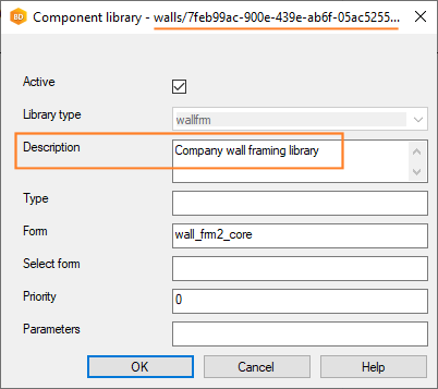
Edit the Description of a Library
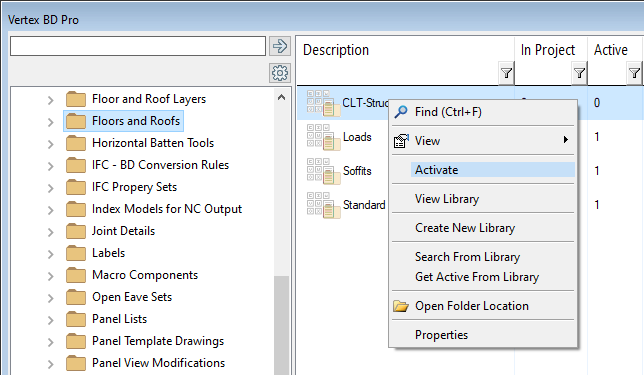
Select Available Libraries
- 1 - The library is available. You can deactivate the library.
- 0 - The library is not available. You can activate the library.
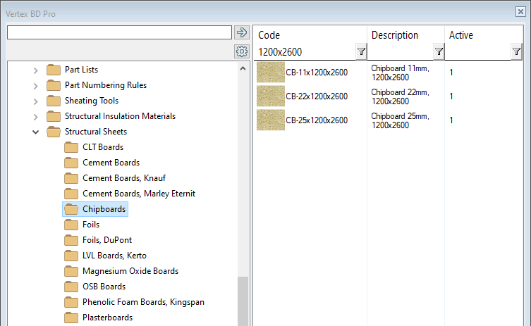
Search for Components in a Library by Filtering Properties
Open the library browser by selecting System | Libraries | Libraries.
- Code
- Description
- Active
You can restrict the components displayed in the browser pane by using the column filtering feature. Set a filter by typing a keyword in the filter field, or click the  button and select a keyword from a list.
Search for Components by Filtering Properties
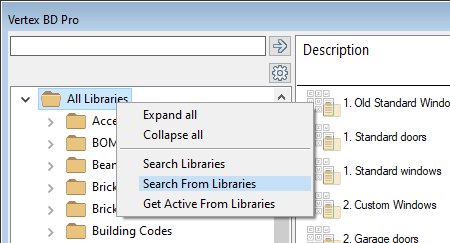
Search for Components by Description or Activity
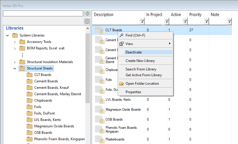
You can search for a component in the library browser by the description of the component. Select a main folder, library type folder or library folder to search. If you want to search standard libraries, your own libraries and project libraries, select All Libraries. Select Search From Libraries from the right-click menu.
You can search for active components by selecting Get Active From Libraries.
Search for a Component by Description
Create a New Library
You can create a new empty library and add components to the library later by copying components from another library of the same type.

Or you can directly select a group of components and copy them to a new library.
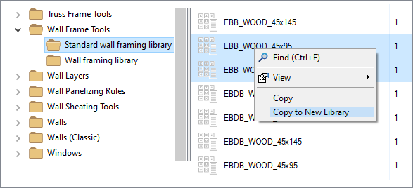
In either case, first select a library of the desired type in the browser. The library can be a standard system library or your own library.
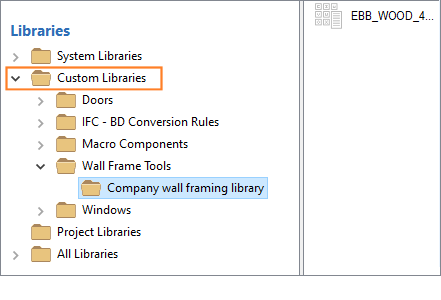
The new library will appear in the browser's Custom Libraries main folder.
Create a New Library in the Browser
Add Components to the Library
Add components to a library by copying components from another library of the same type, and pasting them into your own library. The library you are copying from can be a standard system library or your own library.
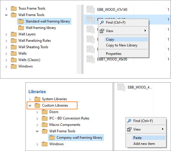
You can also add a new component by selecting Add new item. In this case, the new component does not have predefined parameters.
Edit Component Data
Edit the properties of an individual component in a custom library in a database view. Select a component, and select Properties from the right-click menu.
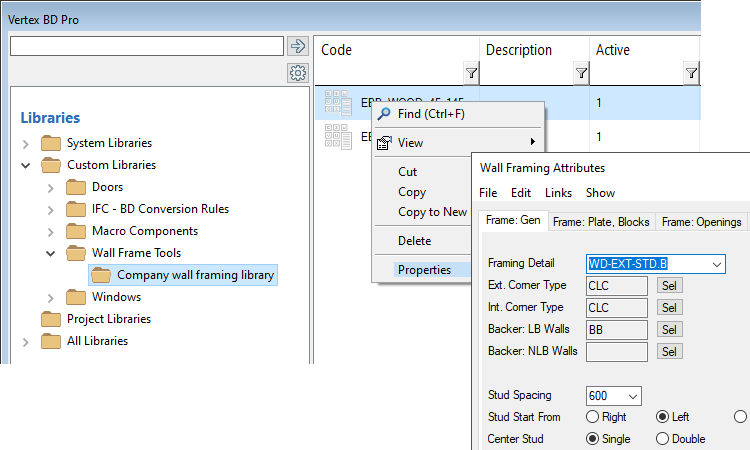
You can view and edit the components of macro component libraries (furniture, building groups, doors, windows) as well as sheet and insulation libraries all at once. Select the library and Edit Library Content from the right-click menu. All the components in the library open for editing in a database view.

Edit the Properties of a Component
Edit the Building Component Library
Edit a Library in a Dialog Box
You can also open a library from the library browser for editing that has its own interface for editing the library and selecting a component. Examples of such libraries are wall libraries and floor and roof libraries. Select the library and Edit Library from the right-click menu.
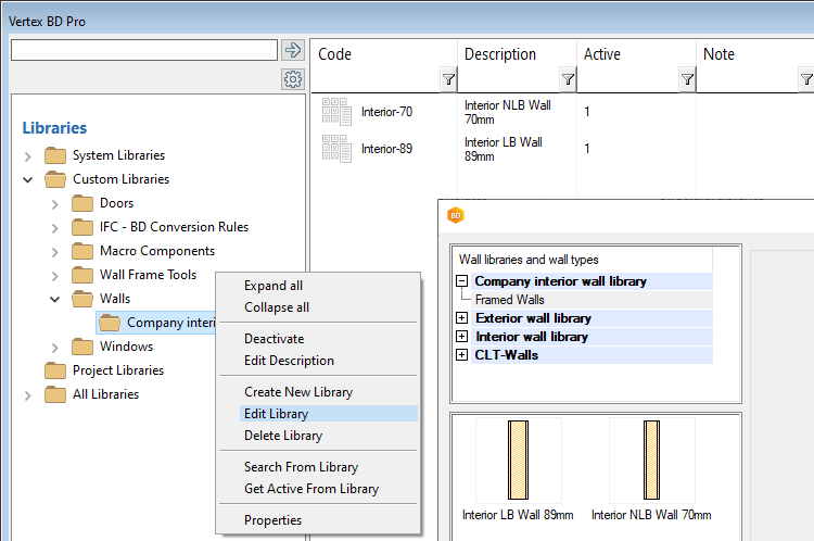
If you do not have your own library, you can also access the same editing interface from the system's standard library. Select the library, and View Library from the right-click menu.
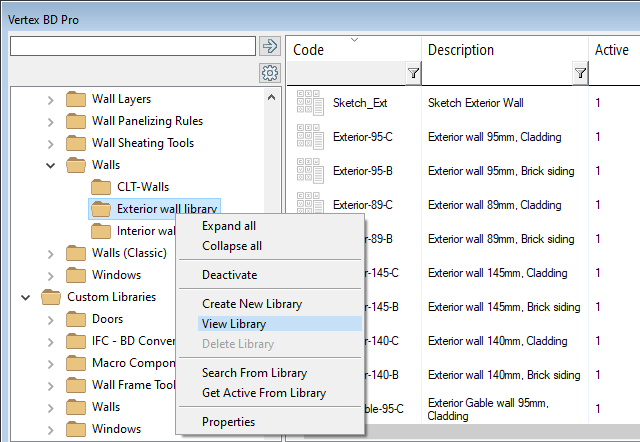
Open a Library for Editing from the Library Browser
Manage Modifications
- Customized - Standard library label. The customer-specific library folder contains individual drawing or model files or ADT programs that overwrite the corresponding standard library files. However, the library database is in the system library folder.
- Overwrites - Custom library label. The customer-specific library folder contains both component drawing or model files or ADT programs and the library database that manages the library. The customer-specific library overwrites the system library.
To find all libraries marked [Customized] or [Overwrites], select All Libraries in the browser, and then sort the content in the right browser pane by the Notes column.
You can view the modifications by selecting the library and Manage Modifications from the right-click menu.

View the modifications in a dialog box.
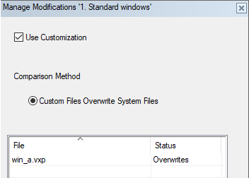
- Use Customization
Customer-specific changes are applied when Use Customization is selected. To disable customer-specific changes and re-enable the system library, clear the check box. In Windows Explorer, the customer-specific library folder is moved to the complibs_obsolete folder, and the system library folder is enabled. The library gets the label Restored in the browser. To re-apply your customer-specific changes, select Use Customization.
- Comparison MethodThe comparison method is "Custom library overwrites system library" in the case of custom library that [Overwrites]. The comparison method is “Custom files overwrite system files” in the case of [Customized] system library. In the case of a project-specific library, you can also choose one of the following comparison methods:
- Custom library overwrites system library
- Project library overwrites system library
- Project library overwrites custom library
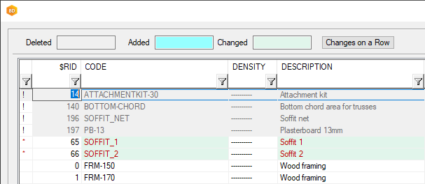
- Check item register modificationsCompare the differences between the database in the customer-specific library folder and the database in the system library folder. The function opens the Show Changes dialog box. Choose what you want to compare:
- Compare structure - Compare the database fields. Choose from the options:
- Compare types and lengths of the fields
- Compare order of the fields
- Compare contents - Select the Relation field, for example the row number $RID, and click Compare. View deleted, added, and changed content marked in different colors in the dialog box. If there are no markings, there are no differences in the databases.
- Compare structure - Compare the database fields. Choose from the options:
- Delete customized item register
Delete the database in the customer-specific library folder. The program will prompt you for confirmation before deleting the database: “System library may be corrupt if current library ui has not been used for previous modifications. Remove customized item register permanently?"
If you are not sure, select No and try disabling customer-specific changes first by clearing the Use Customization check box. Exit reviewing modifications and test the library. If you then want to delete the customer-specific database, reselect the function Manage Modifications, select Use Customization, click Delete customized item register and click Yes.
- File / StatusThe list shows the files in the customer-specific library folder and their status:
- Copy - The file is the same as in the system library folder.
- Local - The file does not exist in the system library folder at all.
- Overwrites - The file is different from the system library folder. In the case of a drawing file (*.vxp), you can compare the changes by selecting Compare changes from the right-click menu. More information on the corresponding function: Show Differences of Drawings.

To delete a file, select Delete file from the right-click menu.
Sheet Library Reform
- 1 - The library is available. You can deactivate the library.
- 0 - The library is not available. You can activate the library.
The browser interface is used when you select a sheet for a sheathing tool or when you edit the properties of an individual sheet and select a new sheet from the library.
Configure a Library
If a standard system library is otherwise suitable for customer-specific use, but you want to change the value of a single parameter, it is not necessary to create your own library and copy the components there. To change the value of an individual parameter, select the component and edit its properties in a database view. This configuration data is stored in the custom folder in an xml file.
- Item
- Default
- Weight/Area
- Surface Color
- Bracing
- Additional parameters
- IFC Property Set
The library will then be marked [Configured].

WORKING IN THE DRAWING AND MODEL WINDOWS
The Zoom of a Floor Plan is Retained
When you zoom in on a floor plan in the active drawing-model pair, the size and zoom of the working window are retained when you switch to another drawing-model pair.
Highlight Alpha Blending
The feature has already been introduced in the 2021 (27.0.02) version.
Possibility to adjust the visibility of the selected object and the geometry in front of it has been added to the graphics settings. With a value of 0, the geometry in front covers the selected object. With a value of 1, the edge lines of the selected object are visible through the geometry in front of it. With a value of 100, the selected object covers the geometry in front of it. With other values, the selected object is partially visible through the geometry in front. In the example figure, the transparency of the selected part is set to 0.
![]()
Define the graphics settings by selecting  >
>  Preferences >
  Graphics. Settings are workstation-specific.
Show 3D Dimensions in Foreground
The view settings for models have a new setting Show 3D Dimensions in Foreground. 3D dimensions and texts are displayed in the foreground when the setting is enabled. The measurement results of the Verify Distance function are always displayed in the foreground regardless of the setting.

ARCHITECTURAL DESIGN
Presentation of End Cap in Free Wall End in the Model
The default value for a free end cap of a wall is defined in the project parameters with the parameter WALL_END_CAP. To change the value wall-specifically, enter a value for the wall property Free End Cap.
- A - The graphics setting Show edges is enabled.
- B - The graphics setting Show edges is disabled.
- C - A rendered model.

You can disable this feature by setting the following keyword in the user/SETUP file: set.free_end.color= 0.

New Sliding Door Components
New sliding door components have been added to the standard door library.

Custom Window and Door Sizes
Previously, it was possible to resize a standard window or door in the selection browser and save the new size to the library using the save button. The library database was saved in the library in the custom/complibs folder. With the new library interface, save buttons have been removed from selection browsers.
However, you can copy the desired window or door from the standard system library to your own window or door library, and modify its properties as desired.
New Size to the Window Library
Floors, Ceilings and Roofs are Added with Layers Expanded
Previously, floors, ceilings and roofs were added so that their representation in the model was a packed basic volume. Now they are added by default with the layers expanded. You can still pack and expand the layers using the same functions as before.
If you wish to add floors, ceilings and roofs in the same way as in the previous versions, i.e. as packed basic volumes, change the value of the keyword layer_auto_unpack to 0 in the system settings:
layer_auto_unpack= 0
Soffits in the Floor and Ceiling Library
Soffits have been added to a floor and ceiling library of their own.

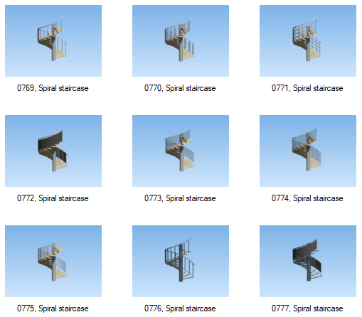
New Components in the Building Component Browser
New components have been added to the building component browser. For example, spiral staircases in the folder Building accessories / Stairs:
In addition, new components in these browser folders:
- Bathroom and WC / Shower walls and boxes
- Building accessories / Fences and gates
- Building accessories / Railings / Glass railings
- Building services / HVAC / Heating
- Courtyard equipment / House equipment
- Furniture / Misc
Create Selection Group
You can create a selection group of components. You can handle the components in a group individually, or you can select an entire group to mirror, move, or copy at once. A selection group can include any component with 3D geometry.
You can save a selection group to the component library by creating a building group from it. You can add a selection group saved as a building group to another project. The selection group property is also retained for the building group.
Create a selection group as follows:
- Select the components in the drawing or model. Select several components by holding down the Ctrl key, or use an area selection.
- Right-click to open the context-sensitive menu.
- Select Advanced > Create Selection Group.
- Type a name for the selection group.
After this, you can select the selection group in the drawing or model as follows:
- Select one of the components in the group.
- Click the + grip point to select the entire group.
Mirror, copy or move the group.
To delete a selection group definition while retaining the components in the group, do the following:
- Select one of the components in the group.
- Click the + grip point to select the entire group.
- Right-click to open the context-sensitive menu.
- Select Advanced > Remove Selection Group.
STRUCTURAL DESIGN
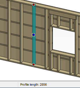
Check the Profile Length or Sheet Size
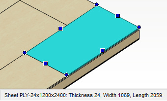
Check the profile length by clicking the profile. The length is displayed in the status bar.
Check the size of a sheet or insulation sheet by clicking the sheet. The size is displayed in the status bar.
Check the Selected Corner Detail
If the wall layer connections do not form correctly in the corners, you can enable the corner detail check when generating the wall panel breaks.
When you generate the wall panel breaks, the program stops at each corner and displays the name of the model file and the hiding group where the detail is stored. The corner is marked with a square symbol in the floor plan drawing.
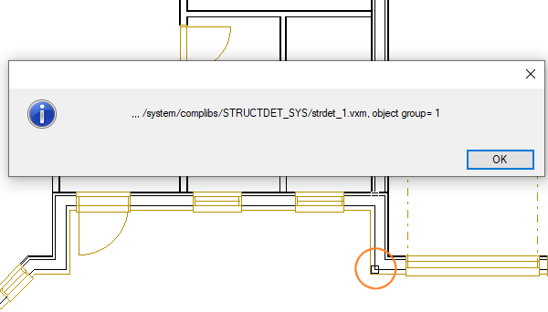
To enable the checking, add the following keyword into the user/SETUP file:
set.corner_config.tell_selected= 1
Restart Vertex.
Check the Selected Corner Detail
Select Sheet in the Browser
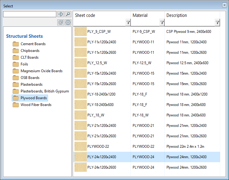
When you select a sheet from the sheet library, the new browser interface is used. In the browser, you will see the available sheet libraries. The library can be a standard system library or a customer-specific library.
Select the sheet library and double-click the desired sheet in the browser. You can first narrow your search results with the column filter function. Set a filter by typing a keyword in the filter field, or click the  button and select a keyword from a list. For example, to filter only sheets of a certain size, type a keyword in the filter box in the Sheet code column. Press the Enter key to filter.
The browser interface is used when you select a sheet for a sheathing tool or when you edit the properties of an individual sheet and select a new sheet from the library.
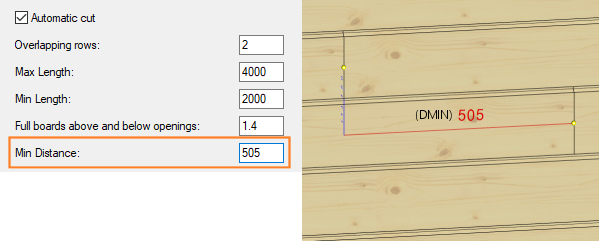
Automatic Cut of Siding Boards
You can enter the minimum overlap for the cut-off points in the Min Distance (DMIN) field.
Move an Overlapping Stud
- adjust_studs_to_studs= 0 - The frame stud is not added at all. This can result in a larger space between studs next to the opening.
- adjust_studs_to_studs= 1 - The frame stud is moved next to the side stud.
Sheet Seam in the Middle of a Double Stud
- sheet_seam_centered_on_dbl_stud= 0 - The sheet seam is located in the middle of the other stud. Default value.
- sheet_seam_centered_on_dbl_stud= 1 - The sheet seam is located in the middle of the double stud.
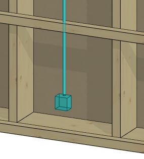
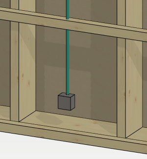
Add an Electrical Pipe
You can add an electrical pipe to a wall panel in the framing model after you have first added an electrical box to the wall in the architectural model, see Add an Electrical Box. A mounting box is added to the framing model for the electrical box, which you can select to add an electrical pipe.
An electrical pipe is a profile that is added from the profile library pipe_electrical.
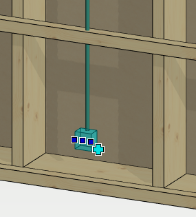
- Select the mounting box in the framing model.
- Right-click to open the context-sensitive menu.
- Select
 Add Electrical Pipe .
 - Select the profile cross section from the Code list.
- Click the points of the pipe's centerline.
- Select Confirm.
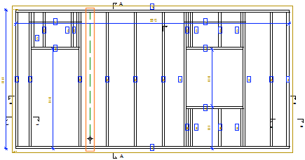
- With a continuous line, when the electrical pipe is on the nearest surface in the viewing direction of the panel.
- With a dashed line, when the electrical pipe is on the opposite side of the viewing direction.
You can generate holes in the frame and sheathing parts of the building according to the pipeline you have added . Select Modeling |  Pipe >
  Generate Utility Holes.
You can create a selection group of the mounting box and electrical pipe that you can mirror, copy, and move in the framing model. Select the mounting box and electrical pipe in the framing model, and then select Advanced > Create Selection Group from the right-click menu. You can then select the selection group in the framing model by first selecting one component and then clicking the + grip point.
You can save a selection group to the component library by creating a building group from it. Select Electrical component as the input style of the group.

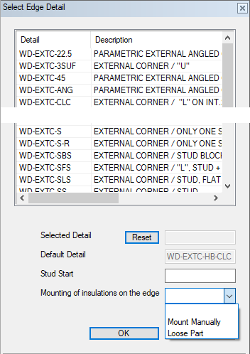
Edit the Edge Detail of a Wall Panel
When you edit the edge detail of a wall panel, the dialog box displays the name of the default detail according to the framing tool in the Default Detail field. You can select a new detail from the list. If necessary, you can remove the selected detail and restore the default detail by clicking Reset.
In addition, you can select the property Mounting of insulations on the edge. Select Mount Manually or Loose Part as the mounting method for the insulation sheet closest to the edge. For example, a loose piece is a piece to be mounted at the building site, a manual piece is a piece to be mounted manually in the factory. The property affects the material collection. You can highlight loose parts and parts to be mounted manually in the model.
Add Lifting Points to a Wall Panel
You can add lifting holes to one or more wall panels. 1, 2 or 4 lifting holes are added depending on the weight of the panel. The panel weight is calculated based on the weight of the wall frame, sheeting, siding, insulation, windows and doors. The lifting holes are positioned according to the gravity point of the panel.
Select Modeling | Panel |  Wall >
  Framing Accessories, and the folder Lifting points.
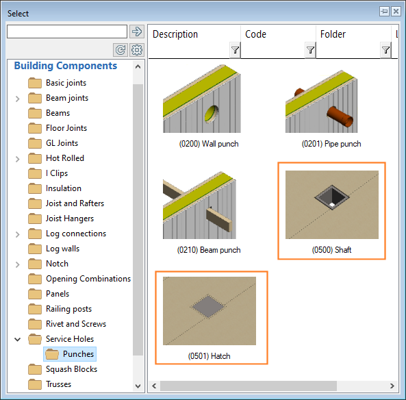
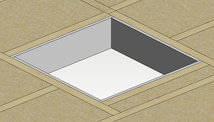
Parametric Punching Components
You can add a shaft or a hatch of the desired size to a floor or roof panel. You can choose whether the component punches the entire structure or just the top or bottom. The component affects the generation of the frame and sheathing. When you add parts to a panel, the program adds the frame parts around the component. An opening is cut in the sheet at the shaft. The sheet is also cut at the hatch, but a piece of the sheet remains at the hatch.
To resize the component, select its properties for editing.
Select the component from the connection detail browser.
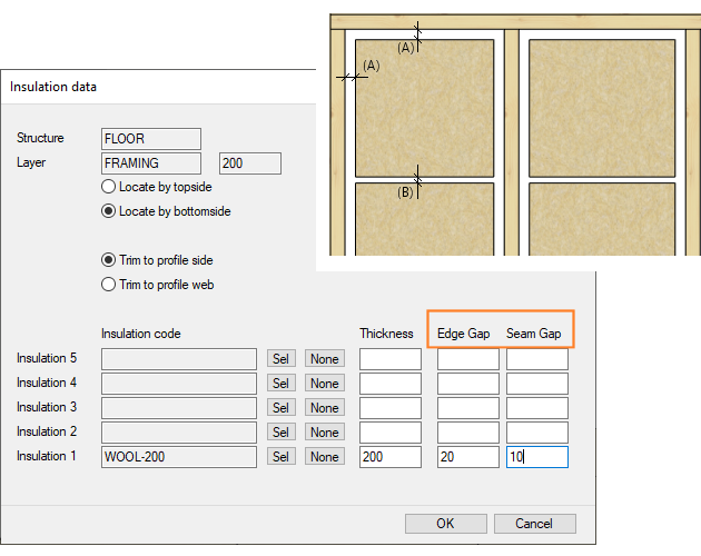
Insulation Installation Gap
When you add insulation to the frame layer in a structure, you can define an installation gap between the insulation and the frame parts in the Edge Gap (A) field. If you selected an insulation with the length of the insulation sheet set in the insulation library, you can also define the installation gap to be left between the ends of the sheets in the Seam Gap (B) field. The structure can be a panel (wall, floor or roof panel) or a floor or ceiling.
Add Insulation to a Limited Area
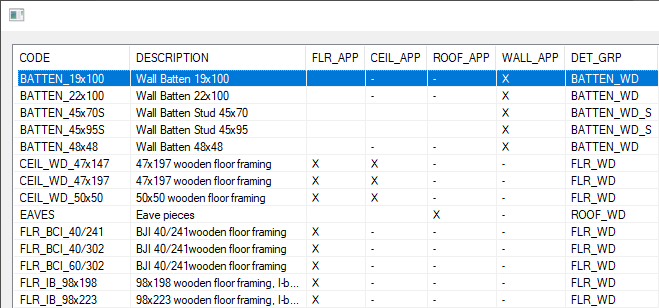
Editing the Frame Tool Library of Floors and Roofs
The user interface for editing the frame tool library of floors and roofs has been renewed.
Select System | Structural Libraries |  Floor and Roof Framing.

You can view a list of all tools by selecting Show > Browse from the menu bar.
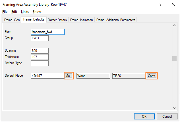
You can change the cross section of the default part by clicking the Sel button on the Frame: Defaults tab. Select the cross section from the profile library. You can also change the cross section of the other parts by clicking Copy. Confirm the selected cross-section, or select another one from the profile library, and then select the parts to change the cross-section from the list. The selections will be updated to the additional parameters of the tool.
Sheets at the Edges of an Opening in a Floor or Ceiling
For the framing tool of a floor or roof, it is possible to define a framing detail that automatically inserts sheets into the structure, for example at the edges of an opening in the structure.
Profiles added to the edges are converted to sheets when parts are generated to the structure.
Select System | Structural Libraries | Floor and Roof Framing. Move to the row of the desired structure and click Details. Move to the row of the desired detail and select the tab Conversions in the lower database view.
- Sheet code - The sheet to which the profile is converted.
- Reference - The parameter can refer to another layer from which the sheet is picked.
- Rule - Defines the position of the sheet if the thickness of the sheet is different from the thickness of the profile.
- In use - The conversion can be enabled or disabled.

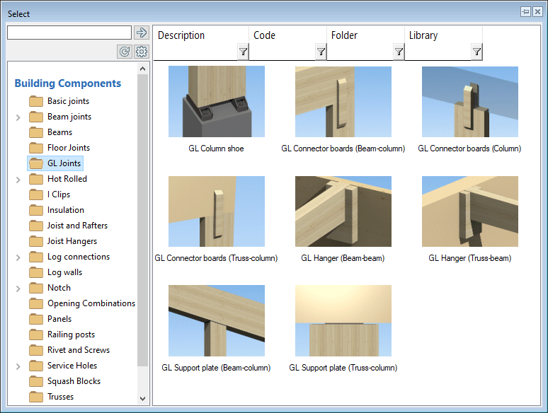
Glulam Joints
New glulam joints are available in the connection detail browser.
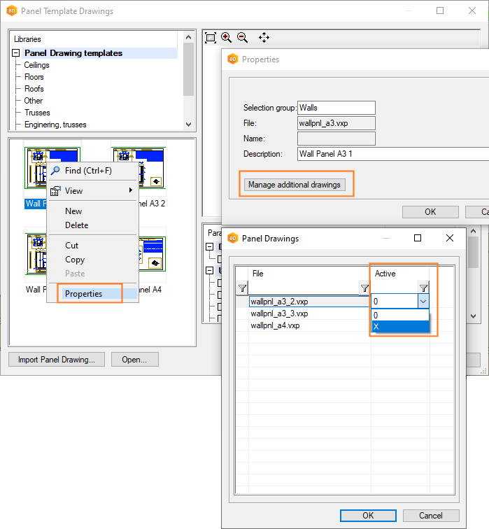
Multiple Panel Drawings from a Single Panel
The usability of the function has been improved. You can select the template drawings that make up the panel drawing set in the library interface. Select the first template drawing in the set and select Properties from the context-sensitive menu. Click Manage additional drawings, and select the second template drawing: move to the row of the template drawing you want in the list, and select X from the list in the Active column.
Multiple Panel Drawings from a Single Panel
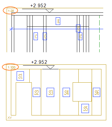
The Size of a Height Symbol in a Panel Drawing View
The feature has already been introduced in the 2021 (27.0.10) version.
The height symbols added to the views of the wall panel drawing are the same size regardless of the scale of the view.
Item Codes to the Panel Drawing Part Schedule
It is possible to add the item codes set to the profiles to the parts schedule of the panel drawing. Enabling this feature requires editing the system settings and the format file that determines the format of the schedule. The available schedules for each panel type are defined in the system settings with the keywords seds_set. For example, the schedules for wall panels:
seds_set= WALL "WPCE|SHT|INS|RIVET|CONN"
The parts to be collected to the schedule, and the format and presentation of the schedule are defined with the keywords seds_param. For example, the wall panel part schedule WPCE:
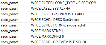
You can add a new keyword to this group:
seds_param= WPCE SCHDL.FLD ITEM_CODE
Also add a column for the item code to the format file that specifies the format of the schedule.
Beam Panel Reference Line Labels in a Panel Drawing View
You can select a presentation with a reference line for the beam panel labels in the properties of a panel drawing view. The panel can be an assembly of beam panels or a panel in which the beam panel is a sub panel.
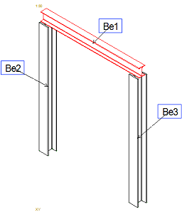
The rules that determine how the part labels are displayed in a view are stored in the component library. The basic software delivery includes the rule library VIEW_LABELS. Select the rule file BEAM_PNL_LBL_LEADER_LINES saved in the library. For a panel drawing of a panel assembly, clear Item IDs in the view properties to disable the default labels.
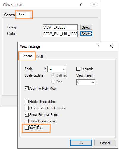
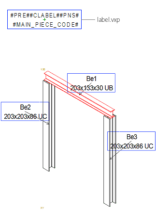
The rule file defines the label library and the label's drawing file to be used. It is possible to display the cross-section code in the label by adding the text macro #MAIN_PIECE_CODE# to the label drawing.
New Dimension Lines to the Panel Drawing Views
Dimensions of a clipped layer
When a wall panel layer has been clipped into areas, you can dimension the area limits by setting the dimension line parameter VALUE to ALL. For example, the parameters of the siding layer of a wall panel:
LAYER(1)=SID|SID~LAYER=0+|SID~PART=AREA|SID~NAME=COVER|SID~VALUE=ALL
When VALUE=ALL, all minimum and maximum points for all defined layers are added to the dimension line. COVER type layers on the outside of the frame are dimensioned with the dimension defined above. For example, a siding layer of type COVER with a pattern design tool added:
Opening trim dimensions
You can dimension opening trims in a panel drawing view by setting the following parameters for the dimension line:
COMMON_MACRO_SIZE|SPLIT|MLIB=[LIB]|MCODE=[CODE]|MTYPE=[NUM]
Meaning of parameters:
- COMMON_MACRO_SIZE - Dimensioning type (mandatory).
- SPLIT - If the parameter is used, a dimension is added separately for each macro component.
- MLIB - Component library whose components are dimensioned.
- MCODE - Components with this code are dimensioned.
- MTYPE - Macro type of the components to be dimensioned.
- MLIB, MCODE and MTYPE are optional. If none is specified, all components displayed in the view are dimensioned.
You can enter wildcards for the value of the MCODE parameter, such as TRIM_TOP *.
- the trims are selected to be attached to the panel when creating panel breaks and
- the trims are visible in the panel drawing view
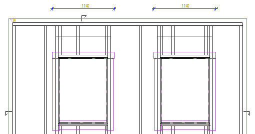
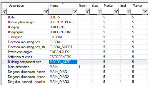
The basic software delivery includes a preset dimension named MACRO_SIZE.
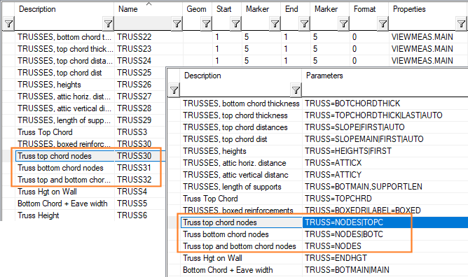
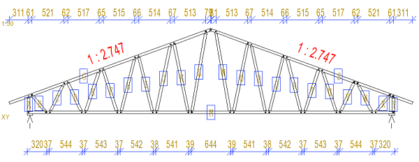
Dimensioning of truss nodes
Three new dimensions have been added to the dimension library to dimension truss nodes.
- TRUSS=NODES|BOTC - Dimensions the nodes of the bottom chord of the truss.
- TRUSS=NODES|TOPC - Dimensions the nodes of the top chord of the truss.
- TRUSS=NODES|BOTC|TOPC - Dimensions the nodes of the top and bottom chords of the truss.
PRINTING
Default Sheet Layout of a Drawing
When you print a drawing and select the sheet size, scale, plot area, drawing position and rotation, you can save these selections to the drawing and use them the next time you print.
Save the selections by clicking Set. After printing, also save the drawing. The next time you print the drawing and want to use the same options, select Use.

Batch Printing with Drawing-specific Printing Layers
When you create a print queue, you can select the printing layers saved in the drawing as the layers to be printed.
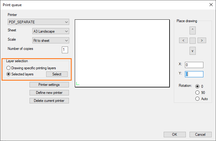
You can select the printing layers by editing the drawing layers with the function View | Layers |  Layers >
  Edit.
Edit.
LOG HOUSE DESIGN
Log House Design is an add-on feature of the Vertex BD software.
New Dovetail Corner for Log Walls
A new corner joint type for log walls has been added to the joint library: 0005 Mitered dovetail corner FF. There are two female dovetails facing each other in the corner.
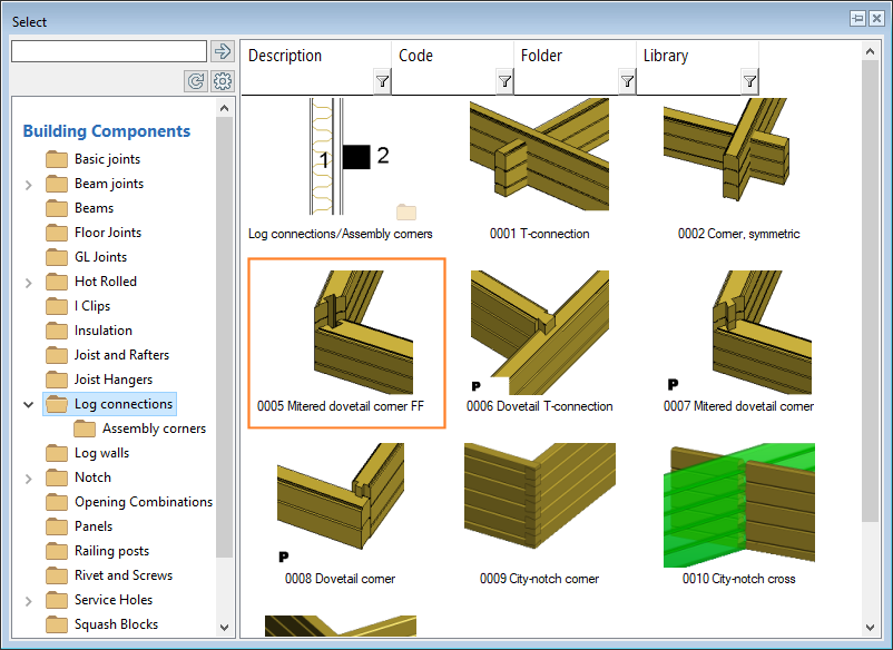
- Select the first wall (A).
- Select the other wall (B).
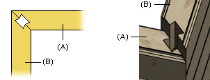 Note: If necessary, re-add the joint and change the pointing order of the walls.
 - Select the joint properties in the Dovetail Joint dialog box.
A new parameter has been added for the dovetail joint. With the Lightening length parameter, you can add machinings to be written to the machining file for sawing a piece out from the outer corner. The parameter value defines the piece dimensions.
- The lightening machining is not displayed in the model or in the log work drawing, but it is added to the machining file.
- Enabling this feature requires customer-fitting.
Drawing Limits of a Log Work Drawing
When you open a log work drawing, the program searches the drawing limits, adding a 10% margin to the limits by default. You can search the limits with a margin of 0.5 mm by setting the keyword search_limits_05marg to 1 in the LOGHOUSE file.
search_limits_05marg = 1
Changing the Log Machining Direction
The log is machined in the direction it is in the log work drawing when endo_mach_list= 1 is set in the LOGHOUSE file. The default is the opposite direction.
endo_mach_list= 1
PUBLISHER
Publisher is an add-on feature of the Vertex BD software.
Print Areas in PDF Outputs
- A drawing sheet with various views of the building added.
- A panel drawing with several different views of the same panel.
Each view can be defined as its own print area. For panel drawings, the print areas are defined in a panel template drawing.
The print area is determined by adding a print area macro from the component library to the drawing. The macro is a drawing file with borders that depict the print area. The print area macro has an additional parameter CODE, the value of which is the name of the print area. For example, the standard delivery of the software includes a print area macro with the additional parameter CODE= WINPLOT. You can add the macro in question as follows:
- Open the drawing. If you want to use print areas in panel drawings, open the panel template drawing.
- Select Modeling | Accessory Component | Component gallery

 Component.
 - Select the folder Drawing Forms / Publisher.
- Double-click the thumbnail image of the print area macro Frame for sheet A3.
- Click a position. Add the necessary number of print area macros.
- Save the file.
Update panel drawings, if necessary.
- You can create your own print area macros by copying the macro from the system library to your own library. Copy the macro WINPLOT from the library System Libraries / Macro Components / Drawing Forms. The macro must have an additional parameter CODE, the value of which is the name of the print area. You are free to choose the name.
Set the Print Areas in the Publisher
In the Publisher, you can set the print areas for the file types PDF book and PDF file. When you set a print area for a PDF book, it is used for all the documents of the book. However, a document in the book can overwrite the book value.
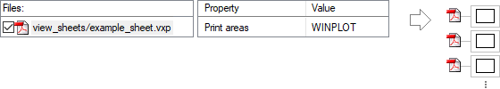
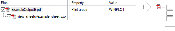
- Add the drawing to a document set as a new document, and select the file type PDF file.
- Add a new PDF book to a document set, and add the drawing to the PDF book. Select the file type PDF file for the document.
Select the property Print areas for the PDF book or the PDF file, and enter the print area macro code as the value, for example WINPLOT.
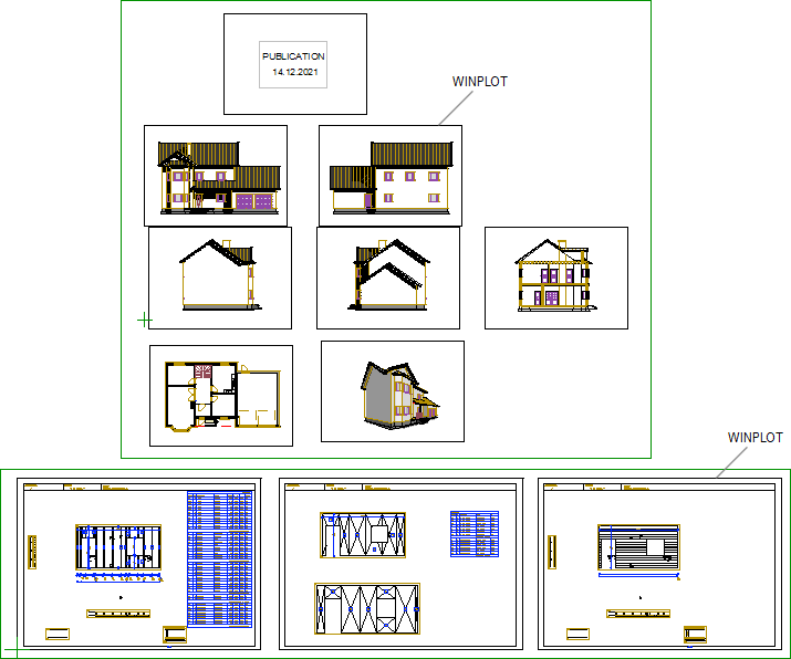
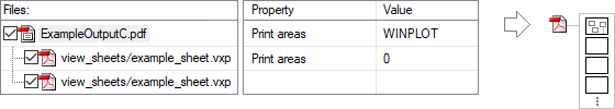
Examples of Outputs
A drawing sheet with various views.
- PDF file with the property Print areas = WINPLOT. In the publication, a separate PDF file is created for each view.
- PDF book to which the drawing sheet has been added as a PDF file. The book has the property Print areas = WINPLOT. The document in the book does not have an overwriting property. The publication creates a single PDF file with the print areas in the drawing printed in it as separate pages.
- PDF book to which the same drawing sheet has been added twice as a PDF file. The book has the property Print areas = WINPLOT. The first document has the property Print areas = 0. This overwrites the book value, and the entire sheet is printed with the print areas ignored. The second document does not have an overwriting property, so the print areas are each printed as a separate page in the PDF. The publication creates a single PDF file, with the first page being the entire drawing sheet and then the print areas in the drawing, each as its own page.
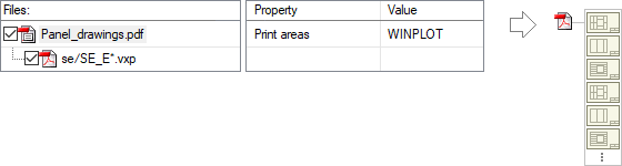
- PDF book to which a PDF file containing drawings of all exterior wall panels has been added (se\SE_U*.vxp). The PDF book has the property Print areas = WINPLOT. The document in the book does not have an overwriting property, so the print areas in each panel drawing are printed as a separate page in the PDF book. The publication creates a single PDF file with the views of each panel as their own pages. The number of pages in the file: (number of panels) x (number of views in the panel drawing).
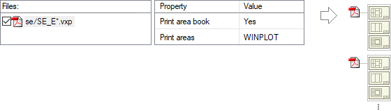
- PDF file containing drawings of all external wall panels (se\SE_U*.vxp). The file has the properties:
- Print area book = Yes
- Print areas = WINPLOT
The publication creates a separate PDF file for each panel, with the views as their own pages.
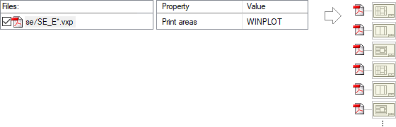
- PDF file with the property Print areas = WINPLOT. In the publication, a separate PDF file is created for each view in panel drawings.
Wildcards When Searching for a File to Publish
You can add multiple files to a document set at once by using wildcards in the file search. The following new wildcards are available:
- $ - one of any letter
- ¤ - one of any non-numeric character
Previously available wildcards:
- * - zero or more of any character (letter, number, special character)
- ? - one of any character
- # - one number
IFC LINK
IFC Link is an add-on feature of the Vertex BD software.
Locate to Point of IFC Model
When you open or import an IFC model, you can select Locate to point of IFC model as the location option. You can use this option in cases where the geometry of the IFC model is very far from the origin of the model. The function searches the point where the x, y, and z coordinates are smallest from the geometry of the IFC model and moves the geometry to the origin of the model using this point as the reference point. You can edit the coordinates of the point in the field. In IFC export, you can move the geometry back to its original location.
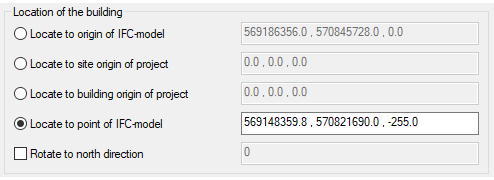
Rotate to North Direction in IFC Export
If the north direction has been defined in the building coordinates, you can rotate the building to the north direction (y axis parallel to north direction) by selecting Rotate to north direction in IFC export. You can also use the feature to rotate the geometry of the building by entering a rotation angle in the field. The angle is calculated in the clockwise direction starting from the positive y-axis.
If the project you are exporting has an IFC model that has been imported using the Locate to point of IFC model option, you can select the Model point property in the IFC export. The geometry of the IFC model is moved back to its original location.

Item Data of G4 Components to the IFC File
With the exception of pipe parts, IFC property sets cannot be set interactively for G4 components. However, writing the item data of G4 parts and assemblies as IFC property sets of their own can be controlled using the xml files in the system/setup/ifc folder.
- ifc_props_part.xml - G4 parts
- ifc_props_assembly.xml - G4 assemblies
- ifc_props_profile.xml - G4 profiles
If you want, you can copy the files to the custom/setup/ifc folder and edit them to include the fields and identifiers you want.
IFC Property Set for the Brick Objects of the Pattern Design Tool
Pattern Design Tool is an add-on feature of the Vertex BD software.
The brick object used in the pattern design tool is written to the IFC file in the same way as the other components. Brick objects have their own IFC property set in the Vertex property set library. For bricks in the Cladding Bricks library that comes with the basic software delivery, this property set is set by default.
You can also add a property set interactively in the building model. However, interactive addition is not a recommended method due to the large number of bricks.
IFC Property Sets Support the COMP_USE Classification
It is possible to add a COMP_USE classification to IFC property sets. When a COMP_USE classification has been added to an object and a property set containing the classification has been set for it, the classification information is written to the IFC file.
- Add a COMP_USE classification to the IFC property set of a door. The property set can be a customer-specific Vertex property set or a user-defined property set.
- Add a COMP_USE classification ENTRANCE for a door.
- Select the property set to which you added the classification for the door.
- ENTRANCE is updated as the value of the COMP_USE property.
Add a COMP_USE classification to a property set:
- Open the property set for editing. The property set can be a customer-specific Vertex property set or a user-defined property set.
- Fill in the data:
- Type COMP_USE in the Property field.
- Leave the Reference field empty.
- Type COMP_USE in the Value field.
- Select String in the Type field.
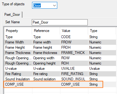
- Confirm by clicking OK.
Add a COMP_USE classification for an object:
- Select a door.
- Right-click to open the context-sensitive menu.
- Select Advanced > Set Classification.
- Click New.
- Fill in the data:
- Type COMP_USE in the Type field.
- Type ENTRANCE in the Classification field.
- Type a description for the classificatino in the Description field.
- Close the dialog boxes by clicking OK.
Select the property set to which you added the classification for the door:
- Select a door.
- Right-click to open the context-sensitive menu.
- Select IFC Property Sets.
- Select the property set to be used.
ENTRANCE is updated as the value of the COMP_USE property.
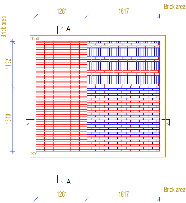
PATTERN DESIGN TOOL
Pattern Design Tool is an add-on feature of the Vertex BD software.
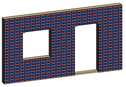
The pattern design tool is a framing tool that allows you to generate bricks according to different patterns. It can also be applied to the laying of other similar parts on a flat surface. You can show the bricks in the panel drawing and collect them in an Excel report.
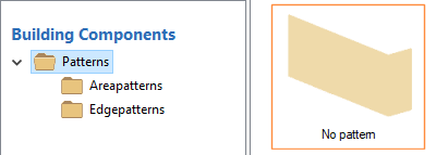
You can add a pattern design tool to the cover or siding layer of a structure. There are two different types of patterns: area patterns and edge patterns. You can select an edge pattern for the edges of an area or opening. It is a good idea to first divide the layer so that the area and edge patterns match.
- Brick Layout Tools - Pattern design tools that you can select for a layer in a structure.
- Cladding Patterns - Brick patterns that can be created with the tools.
- Cladding Bricks - Brick components used in the patterns.
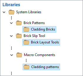
If necessary, enable the library Brick Layout Tools by activating it.
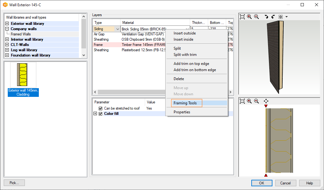
You can add a pattern design tool to the cover or siding layer of a structure. The structure can be a panel (wall, floor or roof panel) or a floor or roof with layers expanded. Add a pattern design tool to a layer in the same way as other framing tools, see Framing Tools.
For example, add a pattern design tool to the siding layer of a wall:
- Select a wall.
- Right-click to open the context-sensitive menu.
- Select
 Properties.
 - Select the wall layer in the dialog box.
- Right-click to open the context-sensitive menu.
- Select Framing Tools.
- Move the cursor to the empty list in the Framing Tools dialog box.
- Right-click to open the context-sensitive menu.
- Select
 New > Pattern Design Tool.
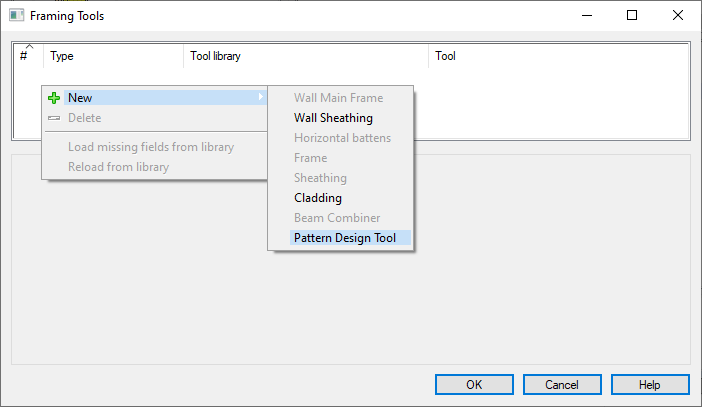
- Select Tool Library.
- Select Tool from the list.
- Select the tool parameters.
- Generate the wall panel and add parts. The bricks appear in the framing model.
- Edit the framing tool, if necessary.
Pattern Design Tool Parameters
Select Tool from the list. If necessary, edit the tool parameters in the dialog box.
Frame: Gen
- Name, Description
- The name and description text of the pattern design tool stored in the library.
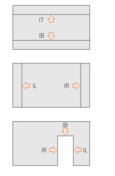
- Brick 1, 2, 3
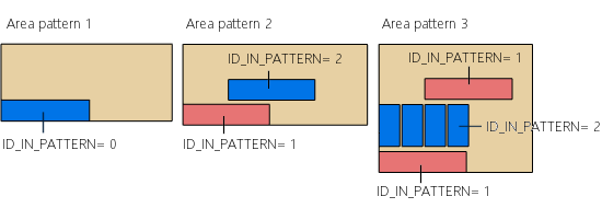
- Click Select to select the brick components to be used in the patterns. The pattern model includes a base pattern consisting of one or more brick components. The brick can be a normal brick (NORMAL_BRICK) or a corner brick (CORNER_BRICK). When you add parts, the brick components in the base pattern are replaced with the selected bricks. The property ID_IN_PATTERN has been set for the brick components in a pattern model. The replacement brick is determined by the value of the property:
- ID_IN_PATTERN= 1 - Brick 1 is used.
- ID_IN_PATTERN= 2 - Brick 2 is used.
- ID_IN_PATTERN= 3 - Brick 3 is used.
- ID_IN_PATTERN= 0 - The first brick of the type in question (NORMAL_BRICK or CORNER_BRICK) is used.
- Fixed patterns
- Select Fixed patterns to retrieve the size of the base pattern's bricks and the gaps between them from the pattern model. Otherwise, the size of the brick is determined by the selected brick component, and the gaps between the bricks by the values in the Brick, Gap Horizontal and Brick, Gap Vertical fields.
- Pattern
- Select the pattern model by clicking Select. Here, select an area pattern. When you add parts, the area is filled by repeating the base pattern in the pattern model.
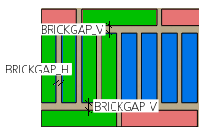
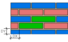
- Pattern, Gap
- Enter the gap between the base patterns in horizontal and vertical directions.
- Pattern, Gap Horizontally (GAP_H)
- Pattern, Gap Vertically (GAP_V)
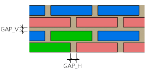
- Brick, Gap
- Enter the gap between the bricks in the base pattern in horizontal and vertical directions.
- Brick, Gap Horizontally (BRICKGAP_H)
- Brick, Gap Vertically (BRICKGAP_V)
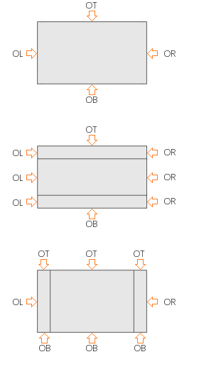
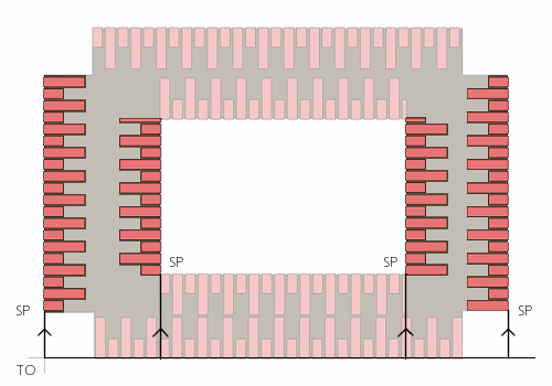
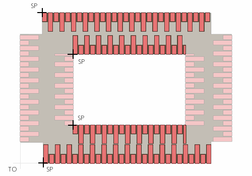
- Origin
- Select the origin of the area where the laying will start. The default is the lower left corner of the area. If the layer is divided into parts, each part forms its own area.
- LOCAL_LEFT - Lower left corner of the area
- LOCAL_RIGHT - Lower right corner of the area
- PANEL_LEFT - Lower left corner of the panel
- PANEL_RIGHT - Lower right corner of the panel
- GLOBAL - Model origin
Outer Edges
- Edge, Pattern
- To select a pattern for each outer edge of the area, click Select. Here, select an edge pattern.
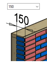
- Move
- Use this feature to define an offset for the starting point of the pattern in the direction of the edge.
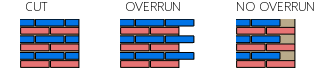
- Cut rule for area / Corner length for edge
- When no edge pattern is selected for the edge, you can select a brick cutting rule for the edge.
- CUT - The brick is cut with the edge (default rule).
- OVERRUN - If the brick extends over the edge, it is added but not cut.
- NO OVERRUN - If the brick extends over the edge, it is not added.
Inner Edges
- Edge, Pattern
- To select a pattern for each inner edge of the area, click Select. Here, select an edge pattern.
- Move, Cut rule for area / Corner length for edge
- Like the outer edges.
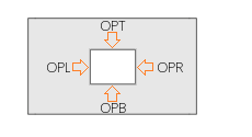
Opening Edges
- Edge, Pattern
- To select a pattern for each edge of the opening, click Select. Here, select an edge pattern.
- Move, Cut rule for area / Corner length for edge
- Like the outer and inner edges.
You can move, copy or delete individual bricks in the framing model.
You can also edit the properties of a brick as follows:
- Select the brick.
- Right-click to open the context-sensitive menu.
- Select
 Properties. You can edit the following properties:
-
COLOR - The color of the brick in a panel drawing view. The color must be defined in the rule BRICK_COLOR of the rule library VIEW_LPROP_RULE.
-
HEIGHT, WIDTH, THICKNESS, WIDTHY - The size properties of the brick.
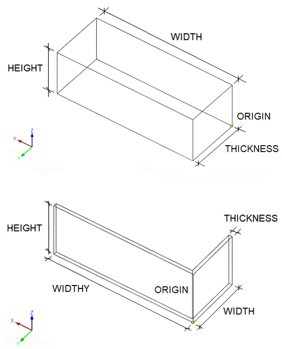 Note: You can mark the non-standard bricks in the model, see Mark Exceptional Parts in a Model.
 -
ID_IN_PATTERN - The property ID_IN_PATTERN has been set for the brick components in a pattern model. The replacement brick is determined by the value of the property.
- SET - It is possible to define the brick components in the library to belong to the same set. All the bricks in the set are different sizes. When the size of the brick in the model changes, the program selects the most suitable brick from the set. Example:
- Brick Blue and Brick Blue Half belong to the same set SetB. The width of Brick Blue is 210 and Brick Blue Half is 100. When bricks are added in the model, Brick Blue Half is used when the width of the brick is less than or equal to 100. If the width is greater than 100 but less than or equal to 210, Brick Blue is used.
The same check is made when the brick is resized by editing the properties. The entire brick component will be replaced if a more suitable one can be found in the set. If the set cannot be found in the library or the appropriate size cannot be found in the set, the size cannot be modified.
-
You can show the bricks in the panel drawing view when you select the 3D presentation method for the layer parts in the view properties.
- Open the panel drawing.
- Select a view.
- Right-click to open the context-sensitive menu.
- Select Properties.
- In Filter, select Layer filter and click Settings.
- Select the properties for the layer "Siding":
- Parts - Select 3D.
- Confirm by clicking OK.
Brick Presentation in the Panel Drawing View
- In the view properties, select the tab Draft.
- Under Library, click Select and select the rule library VIEW_LPROP_RULE.
- Under Code, click Select and select one of the following rules:
- BRICK - Color by code.
- BRICK_COLOR - Color selected in the brick’s properties.
- BRICK_NONSTANDARD - Only non-standard size bricks are shown in the view.
Brick Schedule to Panel Drawing
You can also add a schedule of the bricks to the panel drawing.
- Open the panel drawing.
- Right-click to open the context-sensitive menu.
- Select
 Add View to Panel Drawing.
 - Select the view type Schedule, and the option Bricks from the list.
- Confirm the schedule settings by clicking OK.
- Select a location for the schedule.
CONTROLLING PRODUCTION LINE
Controlling Production Line is an add-on feature of the Vertex BD software. Each production line type requires a separate add-on feature.