New Part Model
You can create a new part model as follows:
- Select
 >
>  New.
New. - Define the document data in the dialog box. Select Part as the document type.
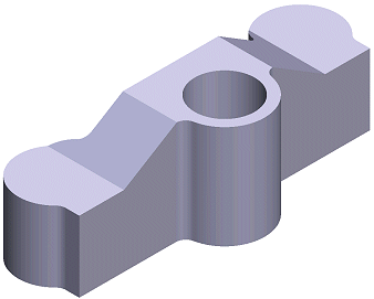
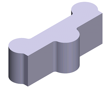
- You can create the part's basic geometry using sketch-based boss or cutout features
(extrude or revolve). Alternatively, you can create the basic geometry by adding a suitable
basic volume as a library feature. Familiarize yourself with the basic concepts of
feature-based modeling:
- Sketching and Geometric Constraints
- Sketch-based Feature
- Feature Tree of a Part
- Machining Feature
- Sketch Library
- Feature Library
You can open detailed modeling instructions by selecting
 > Advanced Modeler
Help.
> Advanced Modeler
Help. - Save the model by selecting >
 Save.
Save. - Select the saving folder and enter a name for the file. If you wish to add a model to the macro component browser, save the model in the folder ../custom/complibs/macro_custom, for example.
- You will be prompted: "Add to model archive?" Select either of the following:
- Yes - You can define various archival data for the model, based on which you can later find and open the model. You can select a previously defined archive card as a template.
- No - No archival data is defined for the model.
- You can return to the building model by closing the part model window by clicking the Close button.

 Note
Note
- If you change the active drawing-model pair or the active drawing-model pair working window during modeling, the application will exit the model editing mode and prompt you with the following question: "Changing drawing-model pair's active window requires model's edit state to exit! Do you want to save changes before you exit?" Save the model by selecting Yes in the message box.
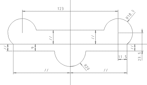
Sketching and Geometric Constraints
When the 3D working window is empty, you can begin sketching a part by selecting a context-sensitive menu function, for example New Sketch > Lateral (YZ) Plane.
Draw a sketch using the 2D drafting functions. You can select functions from the context-sensitive menu or the toolbar. A grid, which can be either linear or polar, makes drafting easier. You can add geometric dimension constraints and constraints for elements to define the relationships between elements and their dimensions. Constraints include coincident, parallel, concentric and equal radius. You can also use the origin and axes of the sketching coordinate system when defining the constraints. The geometric constraints defined in the sketch are displayed as a list in the lower left frame of the 3D working window.
You can later modify the geometry of the sketch using dimensions if you define variables for the dimension constraints. This lets you edit the values of several dimensions at once in a dimension table.
You can save a finished sketch in the sketch library for later use.
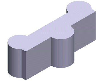
Sketch-based Feature
A feature based on a sketch can have a bossing (add matter) or a cutout (remove matter) function. A sketch-based feature comprises a sketch and an operation performed on it.
Accept the finished sketch using the context-sensitive menu function OK, and select an operation such as a boss or cutout extrusion or revolving.
Feature Tree of a Part
The modeling history of a part is displayed in a feature tree. In the feature tree of the part, the sketch and a boss extrusion form a boss feature. You can later come back and edit both the sketch and the extrusion data, either via the feature tree of the part or the geometry of the part.
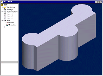
The feature tree of the part will inform you of any situation where the geometric constraints of the sketch are either under or over-defined. The same occurs in a situation where the geometry of a part has been edited in such a way that makes it impossible to create a certain feature.
Machining Feature
You can add a machining feature to a part after you have created the basic shape of the part with a sketch-based feature. Model the machining feature by adding a rounding or a bevel to an edge (line) of the part. Other machining features include shelling and draft.
Select an edge from the part, and then, for example, select the context-sensitive menu function Add Round/Bevel.
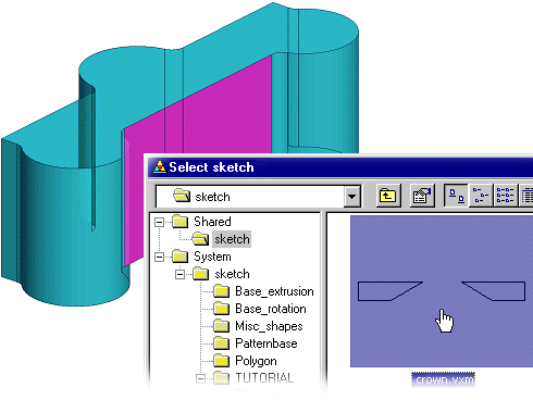
Sketch Library
Most commonly used sketches can be saved in the sketch library. Using an existing sketch speeds up the work and reduces mistakes. Library sketches are selected from a picture menu.
Select the context-sensitive menu function Open Sketch and select a sketch from the library. Select a part surface to which you wish to add a new sketch.
Position the sketch, for example, on the origin of the sketching coordinate system. You can still edit the lines and geometric constraints of the sketch, if necessary. Position the sketch precisely using geometric constraints.
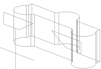
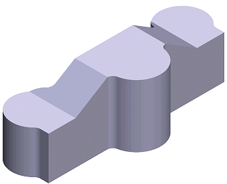
Accept the sketch using the context-sensitive menu function OK, and select an operation, for example a cutout extrusion through the entire volume.
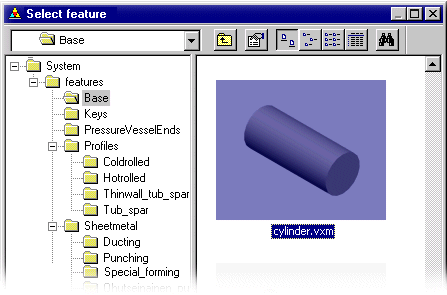
Feature Library
Most commonly used features can be saved in the feature library. A feature added to a part can have a bossing (add matter) or a cutout (remove matter) function. Using an existing library feature speeds up the work and reduces mistakes.
You can begin modeling a new part with a library feature, or add a library feature to the
geometry of a part in the working window. Select Part | Library Feature
|  Cut, for
example. Select the feature from the feature library.
Cut, for
example. Select the feature from the feature library.
Library features are usually modeled using parameters. After selecting a feature, you can edit its geometry by modifying the values in the dimension table. Move the feature over the part surface on which you wish to position the feature. The feature will automatically snap parallel to the surface from its locating point.
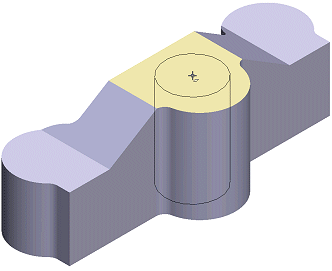
Position the feature precisely in the sketching mode using geometric constraints. Accept the sketch and the feature will be modeled.