
Dimensioning of Walls, Profiles And Trusses
Architectural, Framer
You can use this function to automatically dimension the locations of interior walls, floor joists, roof joists or roof trusses in the floor plan drawing. You can add one dimension line at a time. Select the start and end points of the dimension line so that the dimension line cuts the line of the building component to be dimensioned, for example the framing or sheathing line of a wall.
- Select Drafting | Dimensions |
 Dimension
 Dimensioning of Walls, Profiles and Trusses
 - Select the building components to be dimensioned in a dialog box.
- Select the dimension properties.
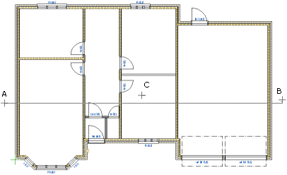
- Select the points of the dimension line. Lock the cursor, if necessary. In the figure below, two points (A and B) of the dimension line have been selected. The dimension line can also be a staggering line.
- If you are adding a staggering dimension line, select horizontal or vertical as the direction of the dimension line. Select the direction from the auxiliary function menu which opens by right-clicking.
 Landscape
 Portrait
- Select the location of the dimension line (C).

Note: The dimension ends for automatic dimensioning are defined in the BDSXX keyword group with the keyword auto_dim_ends.
Note: You can add several dimension lines at once to the floor plan drawing by using the function Dimensioning of Floor Plan. With this tool you can dimension the locations of exterior walls, interior walls, openings and columns. These dimensions are not associative dimensions.