New Projection Dialog Box
The dialog box is opened when you add a new projection model in the drawing.
Select the properties of the new projection.
- Projection Name / Header / Scale / Configuration -
 Projection Name/Header Data
 - Projection – Projection
- Show from Model – Projection
- Drawing Mode – Drawing Mode
- Automatic Dimensioning – Automatic Dimensioning
- Tangential Lines - Tangential Lines
------------------------------------------------------------------------------------
New Projection Dialog BoxProjection Name/Header Data
The projection is named automatically. The name is formed from the name of the model and projection, for example.
- Header
- The title text will be set as the title of the projection. The title is defined when creating a detail view, section view or a new projection. The title text and its position can be edited.
- Move Text from a Grip Point
- Scale
- The default projection scale is 1:1. Select a suitable scale. When the projection is a detail view or a section view, the projection scale will be displayed in the title.
- Scale: autofree or autofix – Dynamic projection
- The projection area can be defined so that it is drawn inside the selected rectangle always, by the function
 Continuous line chain.
  If you draw the rectangle with the function
  Rectangle,
  Open Polyline or
  Closed Polyline, the line chain is not continuous. Make the line chain continuous with the function Line Trimming>
  Concatenate Lines. If you wish to hide the rectangle, move the continuous line chain to layer 110 (hidden layer).
- Concatenate Lines
- You can reduce the size of the projection by reducing the size of the projection line (drag and drop).
- The scales are defined in the settings using the keywords scale -1, Auto free and scale -2 Autofixed. Edit Settings
- Configuration
- Select the configuration for the part displayed in the projection. If in addition to the basic configuration (0: Configuration) there are also other configurations, select the configuration which is displayed in the projection to the field.
- Add a Configuration to a Part Add a Configuration to an Assembly
- Flattening is a configuration of a sheet-metal part. The configuration of a flattening view cannot be changed.
- If you select
 Perspective, automatic dimensioning cannot be selected.
------------------------------------------------------------------------------------
New Projection Dialog BoxProjection/Show from Model/Set Viewing Direction
Select a projection from the list.
As an example: front, top, etc.
Select Show from Model: Indicate the model face to define the direction of the projection.
If you select Perspective, automatic dimensioning cannot be selected.
If you select Set Viewing Direction, define the viewing direction in the dialog box as angle values Alpha, Beta, Gamma and click OK.
The default value iis (A: 0, B: 0, G: 0).
------------------------------------------------------------------------------------
Drawing mode
- Drawing mode
- The default drawing mode of the projection in a model drawing is Wire frame, unless another drawing mode was selected when creating a new drawing from the model. You can also select the drawing mode of a perspective projection in the drawing.
- Advanced
- Can be selected for all other drawing mode except Wire Frame.
- Exact Silhouette Lines
- The silhouette lines (edge lines) are drawn exactly. Coarse drawing speeds up refreshing the projections, but, for example, the dimensioning of an arc will fail.
- Also for spline surfaces
- Precise silhouette lines (edge lines) are drawn for the part's spline faces.
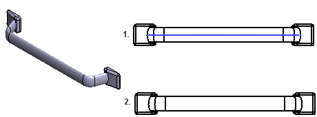
- Center Lines
- Center lines are automatically drawn for circles and arcs. Center lines of the arc will be drawn when the arc sector meets the minimum default value: 180 degrees. You can change the value of the sector projection-specifically. Center lines will be drawn in the projection of a part drawing, even if the
 Center Lines option is unselected when creating a new drawing.
 - You must specifically select Center Lines in the projection of an assembly drawing, if it has not been selected when creating a new drawing of a model.
- The radius is displayed in the projection if Auxiliary geometry is selected.
- Hidden Lines
- The hidden lines are drawn with dashed lines.
- Colored Hidden Lines - You can define the color of the dashed lines being hidden in the Settings. Define the Color of Hidden Lines
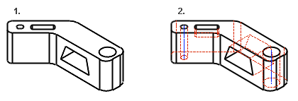
- Auxiliary Geometry
- You can set the auxiliary geometry of a model to be displayed in the projection. Auxiliary geometry is 3D sketches, guide curves, and cross-sections.
- Tool Features
- A machining feature is displayed in the projection if you select Machining Features. The visibility of a machining feature in an assembly has no effect on a projection of a model's drawing.
- Machining Feature
- Also pipe parts
- The center lines of pipe parts will be visible in the projection.
- The visibility of the pipe part center lines is also affected by the projection property Auxiliary Geometry.
- Automatic Dimensioning
- You can add dimensions to an active projection of a drawing automatically.
- Automatic Dimensioning
- Tangential lines
- Apparent shape lines will be created between tangential faces. Select drawing as a shape line or thin line, or disable the drawing of tangential lines in the projection.