
Using a Drawing as a Sketch for a Part Model
You can copy lines from a 2D drawing into a part model draft. For example, you can use this function to convert a drawing into 3D model.
Drawings can include dimensions, but dimensions are not copied to sketches. Vertex adds constraints to sketches with the Automatic Dimensioning function.
You can copy elements of the drawing:
- Active part model (part model in the working window)
- New part model
- New part model in the assembly
As an example, copying lines of a sheet-metal part.
| 2D Drawing | Part Model Sketch |
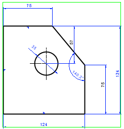 |
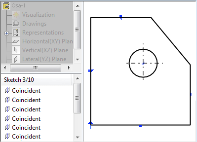 |
Do as follows:
- Select the lines to use in the sketch from the Vertex drawing.
Drawings can include dimensions, but dimensions are not copied to sketches.
- Select the context-sensitive function Copy to Model.
- The Limit Selection dialog box opens. The copied lines are shown in a preview image.
- Projection - Defines the direction in which the lines are viewed in the 3D model: Front, Top, Left, Right, Bottom, or Back.
- Layers - Select the layers in which the lines will be copied. If you want to select particular layers, first select
 Selected layers and select Layer Selection. Alternatively, select All Layers.
 - If you want to limit an area again, click Select Limits. The drawing is displayed in the window where you can indicate the elements in the projection with two corner points.
-
 Automatic Constraints - Vertex adds constraints automatically.
  Dimension constraints are not added. The addition of the constraints may take some time if there is a large number of lines. Dimension constraints are not added. The following text will be displayed in the status bar during the addition: Automatic Dimensioning in Progress.
 - Guide Curve - Creates a guide curve from the lines.
- Explode into Lines - Explodes the drawing into lines (cuts the lines into sections).
- If you want to limit an area again, click Select Limits. The drawing is displayed in the window where you can indicate the elements in the projection with two corner points.
- Click OK.
- Do one of the following:
- If the model window (part model) is open, click the model window. The sketch opens in the window. You cannot bind the sketch to a face of the model.
- Select Accept (V key). The New Document dialog box opens. Name the part and confirm. The sketch opens in a new document.
- If the model window contains an assembly model that does not include the edited part, a new part for the assembly will be created.
- Indicate a location for the sketch.
Select the zero point for the sketch coordinates.
- If necessary, you can modify the geometry, add constraints or remove automatically added constraints.
- Continue modelling with a sketch-based feature.
