You can define the properties of a part, profile part, sheet metal part, composite sheet, pipe component. As an example, data of a part displayed in the drawing.
You can view and edit the part properties after creating the geometry of the part. You can specify archives data for an imported part before saving it in the document archive.
You can only edit the part properties in the model window, not in the drawing.
- Do either of the following:
- Select the part in the working window.
- Select the symbol of a part from the feature tree.
- Select the context-sensitive function
 Properties. You will directly get the part properties for editing by double-clicking the part.
- Edit the part data using the functions in the dialog box.
- Click OK.
Dialog Box Options
- Name (Label)
- The part name displayed is the archive name of the model. The label is defined when creating the part. You cannot change the name.
- You can rename a local part in an assembly. In the part editing mode, you can not rename the part.
- Archives Data
- Click the button and the model archive data of the part is displayed for viewing and editing. If the model is an imported one, you can specify archives data for the part before saving it as an archive document.
- If necessary, edit and supplement the archives data and confirm the data. We recommend defining at least the part code and the name in the model archives data, and preferably also other data. The model archives data of the part is copied to the drawing of the part when the drawing is saved in the drawing archive. When a drawing sheet has been added to a drawing, the archives data will be updated in the header area after updating the drawing.
- Item Data
- Defines the part's item data that is collected in the parts list of the drawing of the part and the assembly. Two windows will open, where you can define item data as follows:
- Item - This item data is collected from the part to the parts list of the assembly.
- Item Structure Data - The structure data is collected to the parts list of the part. If the entire structure is collected to the assembly parts list (roll-out), the parts list will also include the part's material data in addition to the item data.
- Edit and complement item data. We recommend defining at least item label and description in the item data, and also the standard, model, type, quantity and other information. You can retrieve material items to the structure data from the item database.
- The program will add the weight calculation result to the part data and the header area of the drawing when you refresh the projections of the drawing.
- If non-modeled items (so-called Bulk items) such as glue, paint, or fixings, are required to fix a part to an assembly, add these items to the assembly item data.
- By clicking the Transfer to Items button you can save a part into the item database.
- Part Data
- Defines the part's material data, which is collected in the parts list of the drawing. Click the Part Data button, if you wish to add or edit part data. As recommendation the part data is defined with Item Data button.
- This button is displayed, if the keyword set.partprop.partdata= 1 is defined in the file user/Setup.
- To Assembly Parts List
- Sets the compilation of part data into parts lists. This feature is active as a default, and the data will be collected in the parts list. The data will not be collected on the parts list, if
 To assembly part list.
- To Assembly Drawing
- Sets the part to be displayed in the assembly drawing. This feature is active as a default, and the part will be displayed in the drawing. The part is not displayed in the drawing of the assembly, if To Assembly Drawing.
- Reference geometry visible in the drawings of the assembly
- When the
 Reference geometry visible in the drawings of the assembly checkbox is selected, the reference geometry used in the modeling of a part will be visible in the drawing. If the checkbox is cleared, the reference geometry will be hidden. This definition affects all drawings and drawing projections created from the part.
- The reference geometry are 3D sketch, guide curves, and cross-sections, and pipe part center line. In a drawing, you can make the reference geometry of a part visible projection-specifically.
- Table model (multiple items)
- When you create the first configuration-specific item in addition to the 0:Default configuration, the part model will become a table model. The property will be selected automatically in the dialog box.
- If there is a Part Data button in the dialog box, defining the properties for the table model with this button is disabled.
- Machining with feature in assembly
- Defines a part property that allows or prevents the machining of a local part in an assembly. Machining of a part is allowed (default), if Allowed. Machining of part is prevented, if Allowed.
- You can allow machining a link part with a feature, if you select Allowed also as a link. Machining a part in an assembly is prevented when both checkboxes are cleared.
- If you select Makes machining only to parts in same subassembly in the assembly, the part will machine only parts that are in the same subassembly. The machined parts can belong to the same subassemblies also within subassemblies. You can select this property, if you select
 Tool.
Tool.
- Type
- The program will recognize the type of the part in the working window. Click a radio button:
- Normal part
- Profile PartSelecting this type makes the profile design functions available.
- Composite SheetSelecting this type defines the plate part as a composite sheet, which can be one, two or three-layer structure. It is recommended that the part is modeled with the function Extrude Composite Sheet, which defines the part as a composite sheet.With the button Properties you get the composite sheet to edit.
- Sheet metal (Sheet metal part)Selecting this type enables the sheet metal functions.You can change the part type to a sheet metal part, when you are modeling a sheet-like part (Normal part). This change is possible for sheet-metal parts that have been modeled using the Extrude function. Convert a Normal Part to a Sheet-Metal PartIt is recommended that the sheet metal part is modeled with the function Extrude As Thin Feature, which defines the part as a sheet metal part, and as a result the software offers sheet metal design functions.With the button Properties you get sheet metal part parameters to edit.
- Concept PartThe concept part is a technique designed to lighten heavy assemblies. An entire subassembly can be replaced by a single part, which can have sufficient detail for, for example, a layout drawing. This technique enables quick generation of sufficiently accurate drawings for tender purposes with the design automation system.
- Select the part type, and also select:
- ToolThe function define the part entire geometry as the tool. If the part already contains a machining feature, you can define the entire geometry of a part as a tool only when you have first deactivated the tool property of the machining feature. You can do this in the properties of the feature in question. You can also define a part imported to this program as a tool, if you first save it as a Vertex model.
- Flow partThe part is saved in the document archives of the Flow system. The checkbox of the Flow part is selected when you view the properties of a part selected for editing from the Vertex Flow system. If the checkbox is cleared, the part's saving location is the Vertex G4 archive. The contents of the checkbox are changed by the program.
- LampThis function can be used to define as a lamp a part to which pointlights and spotlights have been added with visualization functions. As a library component, the light intensity of a lamp can be adjusted in an assembly.
- Pipe ComponentThis function can be used to define a part as a pipe component. This property is selected, if the pipe component is added from the library. Open the pipe component properties for viewing by clicking Pipe Component Info.
- Properties
- After you have selected part's type, click the Properties button.
- Normal part
- Sheet metal part, see The Properties of a Sheet metal Part
- Composite sheet, see The Properties of a Composite Sheet
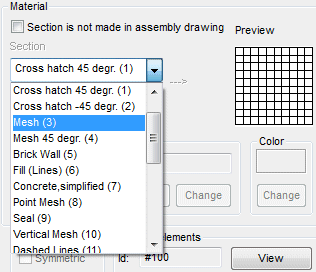
- Section
- Sets the type of the section hatch in the section projection. As selected is the same hatch types, like in the 2D drawing in the adding the hatch. Select the section pattern type in the Section list.
- Old section projections – If you have changed the section hatch in the drawing with the Hatches>
 Hatch function, you can remove the old section hatch in the projection. Then, select the context-sensitive Update function. This will update the hatch defined in the part properties to the section view.
 Update a Drawing
 If the section lines has been selected for the rendering material using the Edit rendering material function, you cannot select any other material in the part properties.
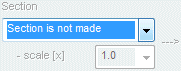
- A part will not be displayed sectioned in a part or assembly drawing's section projection if Section is not made is selected in the part properties. The part will be displayed as a whole.
- A part will not be displayed sectioned in an assembly drawing's section projection if Section is not made in assembly drawing is selected in the part properties. The part is displayed sectioned in the part-specific drawing's section projection.
- Section View
- Scaling
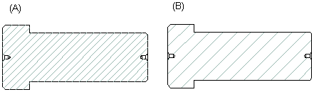
- Sets the scaling of the section pattern. The factor will affect the pitch of the pattern. The default scale factor value is 1. A factor value larger than 1 will increase the pitch. A factor value between 1 and 0 will decrease the pitch from the default value. Select the factor value.
- The section pattern is scaled from the factor 10 (A) to 20 (B). The change will be shown in the drawing as follows:
- Rotation
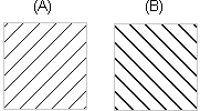
- Sets the angle of the section pattern. A positive angle value will rotate the pattern counterclockwise. Select the angle value.
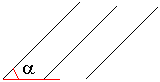
- The section pattern is rotated 0 (A) and 90 degrees (B). The change will be shown in the drawing as follows:
- Rendering Material
- The Name field displays the material added with the Visualization software. You can change a new material and/or edit the shading properties of the material.
- You can select a new rendering material for the part by clicking the Change button. You can edit the shading properties of the material, or create a new material and save to the library by clicking the Edit button. The Save button is not yet in use.
- The material properties are described in the section Visualizing a Model.
- Material Shader Properties
- Color
- Sets the color of a part in the shaded view. Click the Change button. You can set the color as follows:
- From the color paletteYou can choose to view the colors by hue or in numerical order. The old color and the new color selected will be displayed in the dialog box. Select the color from the palette and confirm the data.
- Use the Default ColorThe program will create a shaded view of a model in the default color if you do not define the color from the palette. The default color has been defined in the software settings. You can restore the default color by clicking the button and confirming your choice.
- If the Visualization software is in use, the part will have a default material. You can select the new material from the material library.
- Symmetrical
- Symmetry affects the assembly function Mirror Part. You can define a part as possibly symmetrical
 , asymmetrical or symmetrical . The default is possibly symmetrical.
- A part defined as symmetrical will retain associative with the original model after mirroring. If the checkbox is empty, the part is not symmetrical, and a mirror image is created of the part during mirroring.
- If a part has not been specifically defined as symmetrical or asymmetrical here, it is possibly symmetrical. A mirror image of the part is created during mirroring.
- Named elements
- You can view named elements of the part by clicking the View button. This is a property of the design automation system.
- If necessary, you can edit named elements by selecting the label of the part form the feature tree and the context-sensitive function Other Functions> Edit named elements.
- Edit Named Elements
