
Model a New Profile Feature
Model a profile feature as a part model containing only a single cross section feature.
 Always create the sketch in the Horizontal(XY) Plane.
When sketching a profile feature, note that the origin of the sketch is the default reference point of the feature, and the plane determines the alignment of the feature. For this reason, handles do not need to be added to profile features, unlike regular library features.

Model a profile feature as a single feature.
- Start creating a new part.
- If you wish to save the part in the archive, enter a label for the part.
- The feature will be named when the profile feature is saved in the library. The name can be different from the part label.
- Select the context-sensitive function
 New Sketch> Horizontal(XY) Plane.
- The origin of the sketch will be the default reference point of the profile feature.
- The normal of the cross section face will be parallel with the Z axis. When modeling a profile part in an assembly, the normal of the cross section will be parallel with the guide curve.
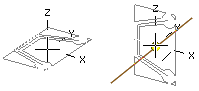
- Draft the sketch of the profile cross section with shape lines.
- The sketch is a closed polyline.
- Draw the web of the profile vertically in the direction of the Y axis.
- Add guide lines in the same sketch for positioning the feature.
- You can select points from the guide line for alternate reference points for the profile feature.
- Add geometric constraints and define variables for the dimension constraints.
- You can test editing the sketch with the Dimension Table function.
- Select the context-sensitive
 OK, and select Cross Section as the operation.
- You do not have to add a handle, because the origin of the sketch and the XY plane determine the positioning and alignment of the feature.
If the feature has more than one history step, saving as a profile is disabled.