
Cross Section on a Guide Curve
Profile Structure Design
Sweep a cross section along a guide curve.  Guide Curve
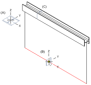
- The cross section selected from the profile library is displayed in the working window (A).
- When you move the cross section over a line of the guide curve (B), it is positioned perpendicularly to the line.
- You can then rotate the cross section, if necessary, and select the line. The cross section is displayed in the profile part (C). It is positioned at the point you clicked on the line.
A profile part created this way is a part fixed to the assembly.
- Select one of the following:
- On the
 tab, in the Add group, select
  Add Profile. (G4).
 - On the
 tab, in the Steel Structures group, select Add Profile. (G4 Plant).
- On the
- Select a profile cross section from the library. Browse - Archives
- Select the table ID determining the profile size.
- If necessary, attach item data to the profile part.
- Move the cross section to the guide curve line.
- You can rotate the profile cross section or change the position of the insertion point by selection an auxiliary function.Change the Reference Point Rotate a Cross Section Change the Insertion Point
- You can select the function that will trim the profile automatically to a face or to edge.Automatic Trimming of a Profile Part to a Face Automatic Miter Joint of a Profile Part
- Select a line from a guide curve as the position of the cross section. Note that the cross section will be positioned on the point you click on the line.
- Select Confirm.
Note:
- You can also select a line on an existing profile part as the position of the profile cross section. Profile parts created this way are also fixed parts. The same is true of profile parts you position in starting and end points.