
Reference Grid
Piping Design
Define a reference grid (module network) to assist the design process. The reference grid uses a database as its basis.
Note: Press Shift+left mouse button on the  Define Reference Grid function. Follow the video help
Define Reference Grid function. Follow the video help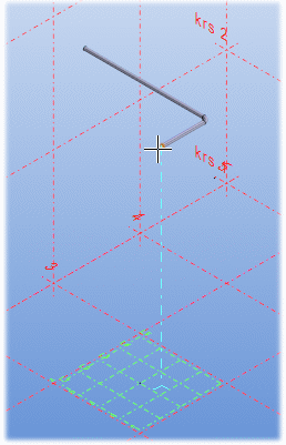
- On the
 tab, in the Tools group, click
  Define Reference Grid.
The REFERENCE LINE DATA dialog box is opened.
- Add a grid line by clicking Add Grid Line.
- Define the direction /X, Y or Z), text and distance to origin (mm).
- Specify properties in the tabs:
- Name –Name the reference grid.
- Origin – Click Select from Model and indicate the position of the origin.
- Rotation – Enter the rotation around the Z axis as a value of the angle or click Select from Model.
- Texts – Text height (mm), line width, font, scale, color.
- Lines – scale, width, type, extension (mm), color.
- Select OK.