Create a New Piping Component
Piping Design
You can save a part model as a piping component.
- A part model modeled with the Vertex G4 application.
- A part model downloaded from the Internet.
In the definition of a piping component, the number and content of the work phases vary based on which kind of part model is saved in the component library. The model can be one of the following.
- A parametric Vertex model. The model includes a dimension table.
- A non-parametric Vertex model. The model does not include a dimension table.
- A part model imported into Vertex as a file. The file is in some file format other than Vertex file (vxm).
You can also save a Vertex assembly model as a piping component.
Work Phases
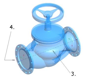
The image’s valve is imported with the Vertex Import function as an SAT file for example. In order for the component to behave in the desired manner as part of a pipeline, you need to define a center line and connection handles for it.
Work Phases:
- Replace line styles to pipe lines by selecting a line type Pipe from a group Style.
- Change the part’s type to Normal and Pipe Component from the part's properties.
- Add a center line as a 3D sketch. Pipe Center Line is set as the line property, as a default.
- Add handles to the ends of the center line and select Pipe connection as a handle property.
 Add a Center Line and Handles to a Part Model
- Save the part as a piping component. The parts marked with an asterisk are required.
- If you want, you can create a part with dimension variations from the part.
 Create a Dimension Table (3D)
