
Profile Part Modeling - G4 Mechanical Engineering
Profile Structure Design
A profile part is an assembly feature that is modeled in the assembly. You can only select profile part modeling tools in an assembly model.

Profile Cross Section and 3D Sketch
The shape of the profile part is based on a profile cross section (profile feature) that is selected from the profile library. The size of the cross section is defined by selecting a table ID that determines the variable values. For some cross sections, the values are directly entered. After defining the size, the cross section is displayed in the working window.
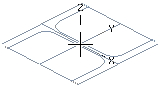
The cross section is positioned using its insertion point, the position of which can be changed if necessary. A separate window opens for the selection of a new insertion point. Select a point as the new insertion point.
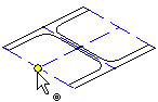
The position of the cross section changes when it is dragged from its insertion point to the position, line or face selected for it. If necessary, you can rotate the cross section before modeling the profile part.
Add a profile part by clicking two points. The finished profile part will comprise a cross section and a line which is a 3D sketch. The 3D sketch is positioned between the two clicked points, and a Distance constraint is automatically added to the sketch line.
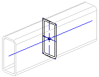
If the profile part length is determined by assembly geometry, for example a guide curve, the 3D sketch is created based on the guide curve and the Distance constraint will not be added, because the guide curve determines the length of the sketch line.
You can use a sketch line to change the length of a profile part added freely, position a cross section between the ends using different reference points, etc.
 A 3D sketch must not be removed from a profile part.
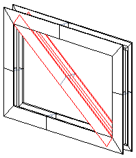
Profile Sweep
A skeleton formed of a guide curve is utilized in designing a profile part. Its shape can be easily modified, because it is based on a parametric sketch, the dimensions of which are easily modified. A profile part is associated with the geometry to which it is attached.

Select a suitable cross section from the profile library and sweep it along the guide curve line to create a profile part. The cross section is automatically set perpendicular to the line. Select a line from the skeleton - the cross section is placed on a point on the line and the profile part is modeled. The skeleton determines the length of the profile part and its 3D sketch.
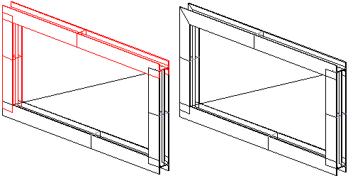
Other alternatives for modeling a profile part are: adding the cross section to a point in a model, between two points in a model, to the line of an existing profile, or to a planar face. Profile parts added in this way have external references and are highlighted in blue in the assembly tree, for example  .
.
The cross section of a profile extruded between two points can have a different insertion point at the starting point than at the end point. The insertion point is changed before selecting the end point.
A profile part forms a fixed part of an assembly when the cross section is swept along a guide curve, between two points, or a profile line is selected as the starting point.
If you cannot accurately determine the position of a profile part when it is modeled, it is positioned in the assembly using geometric constraints. If necessary, you can fix it in place.
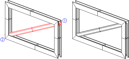
Trimming
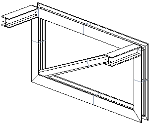
Two parts of an assembly are trimmed to form a miter by continuing and/or shortening the parts. The ends of both profile parts are trimmed to form a miter.
Another way of trimming a profile part is to select one part from the assembly and trim both of its ends.
The ends of the profile part are indicated with the numbers 1 and 2. This makes it easy to select the parts or faces to which the ends of the selected profile part are trimmed. End 1 of the profile part is trimmed to fit two parts selected from the model.
Editing
A profile part can be edited in an assembly as follows:
- Restore the original geometry of the profile part, in other words delete the trimmings by selecting the assembly part and sweep for editing.
- Edit sweep data such as elements selected for the sweep, elements that are used for trimming, or the offset.
- Edit the 3D sketch of a profile part.
- Edit the cross section sketch.
- Relocate a cross section using its reference points.
After editing a skeleton and/or profile, the external references can be solved for the parts selected from the assembly or the entire assembly by selecting the  Solve function.
Parts List Data
Parts lists will include the cutting lengths and the cutting angles of the ends of profile parts in two directions. Item data is listed if it has been defined.