Add Constraints for the Elements in a Model Sketch
The purpose of sketching is to create a rough sketch of line elements. We recommend drawing the sketch in approximately the correct proportions.
The sketch can be made more accurate by adding constraints for defining the relation between the elements and dimensioning the elements.
Constraint Types
Constraints are defined for the elements in a sketch in order to enable the editing of the sketch. The available constraints for the elements include distance, radius and angle constraints, for example. These driving dimensions can be used to control the size, direction and position of the elements in relation to each other. In addition to driving dimensions, you can also add the other geometric constraints to a drawing.
Dimension constraints:
Other geometric constraints:
Using Functions to Define Constraints
The functions for defining the constraints can be used in two different ways. You can select the functions from either the context-sensitive Constraints menu or the toolbar. The options for using a function are:
- Option 1: First select the constraint and then the elements to be affected by the constraint.
- Option 2: First select the elements to be affected by the constraint. Remember that you can select several elements by holding down Ctrl while clicking with the left mouse button. Then select the constraint. This option cannot be used for some constraints, for example, Equal Distance.
Option 1 provides a beginning user of the software with prompts that assist in using the functions. Option 2 provides an advanced user with a quick way of defining constraints.
For what kinds of elements can constraints be used?
- Constraints can be defined for line elements and points in a sketch.
- The axis and origin of the sketching coordinate system can also be added to the constraint.
- When adding a sketch to a reference face, the edge of the reference face can be added to the constraint.
- You can add the constraint to a line or a point that exists as a phase prior to the sketch in the geometry of the part. Constraints cannot be defined for future geometry.
- If you are modeling a part in an assembly, you cannot define constraints for the geometry of other parts.
 Add Constraints to a 3D Sketch
Adding a constraint automatically
- The program will automatically add a constraint to an element when drawing if it is possible to realize a constraint when positioning an element in relation to another element, such as Coincident, Concentric or Perpendicular.
- For instance, you can draw a circle by selecting the center point of an existing circle as its center point in the sketch. The program will make the center points of these two circles concentric. Correspondingly, when you select the center point for a circle by clicking on a line, the center point of the circle and the line will be made coincident, etc.
- The dimension constraints and graphical symbols of the other constraints are displayed in the sketch. Visibility of Geometric Constraints
Fixing a sketch using geometric constraints
- You can fix a sketch to the axes or origin of the sketching coordinate system using geometric constraints. For example the sketch line can be coincident with the axis of the coordinate system, and you can define the distance between the line and the origin, etc.
- You can fix a sketch to the sketching coordinate system by making the rotation axis coincident with the vertical axis of the coordinate system.
The rest of the sketch is defined using dimension constraints in relation to the rotation axis. Other constraint types that can be defined for a sketch include Perpendicular and Angle.

- When adding a finished sketch from the library to the reference face of a part, for example, it is positioned using its origin. Positioning the sketch using geometric constraints is important, as it will insure that the correct position of the sketch is retained later when editing the geometry of the part using the dimension table.
Parametric Sketch
You can add a variable to the dimension constraint of a sketch. A dimension, for example a distance dimension, is depicted using a variable. In practice, a variable is defined for geometric constraints in addition to numerical values. After this, the sketch geometry can be edited with the dimension table.
Viewing the constraints of a sketch
You can view the constraints defined for a sketch. The list of constraints for the sketch is opened for viewing in the feature tree of the part when you open the sketch for editing. Unsolved constraint is highlighted in red color.
The elements affected by a constraint will be highlighted in the sketch.
Feature Tree of a Part Feature Tree Symbols and Conventions
Unrealized Constraint
- A dimension constraint and other geometric constraint is highlighted in blue color when the geometric constraint is valid.
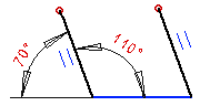
- In the drawing, unresolved constraints will be highlighted in red color. For example, if too many constraints are defined for elements, the sketch is overdefined and the color of the constraint changes to red.
In the image below, the other dimension constraint is extra. You can fix the situation by deleting the extra constraint.