
Modeling Windows
Windows are modeled on the XZ plane as assemblies the origins of which are in the upper left corner and in the middle of the frame in the depth direction. Model windows as lightly as possible, avoiding unnecessary history steps.
Line width and layer
The line width of lines should be 0.13.
- The line going around along the outer edge of the frame is added on layer 101. The opening in the wall is formed based on this line.
- It is possible to add a line to the layer 1001 on the basis of which the opening is formed in the wall siding layer. It is required that the parameter Siding overlaps on openings in the wall properties has the value 1. For the other layers, the opening is formed according to the line at level 101.
Surfaces
Windows have the same surface naming practice as doors.
Variables
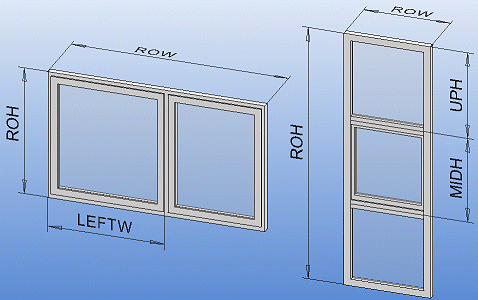
Windows can be fully variable. The basic variables are width (ROW) and height (ROH), from which all other widths and heights are calculated using dimension variable formulas.
Frame
The first part to be modeled is the frame, modeled in the same way as with doors. The origin must be in the middle of the frame, in the upper left corner as seen from the outside. The window may not move in relation to the origin when the dimensions change.
The frame's width variable is ROW and the height variable is ROH. The frame is extruded in both directions. The extrusion thickness is FRAME_THICK.
Name the frame surfaces as follows:
- Exterior wall surface CASE_EXT
- Interior wall surface CASE_INT
Once the frame has been extruded, a line going around the outer edge of the frame is added to it. This line is added on layer 101. When the window is added to the building model, the program will create a hole in the wall based on this line. The line is created as its own sketch on the frame surface, and made into a guide curve.
Sash
The window sash(es) and the glass panes form a subassembly. Model the sash and glass pane and fix them together with constraints. Name the sash surfaces as follows:
- Interior surface BODY_INT
- Exterior surface BODY_EXT
Name the glass pane surfaces as follows:
- Exterior surface GLASS_EXT
- Interior surface GLASS_INT
Multiple-light windows
If there is more than one opening in the window frame, you must define separate variables for the openings. For a vertical window, for example, UPH and MIDH, and for a horizontal window LEFTW and RIGHTW.
- The assembly modeling requires the Advanced 3D Modeling add-on option.