
Punch Using a Pipe in the IFC Model
IFC Converter
You can punch a structure using a pipe in an IFC model. The structure can be a wall panel, for example. The pipe in the IFC model must be of the IFC object type IfcFlowSegment. Only round punches are currently possible.
Note: Requires that the IFC model has been imported with Vertex BD 2023 (29.0) or a later version that uses the ODA tool for IFC import.
Importing an IFC model requires the add-on option IFC Converter of the Vertex BD software.
After you have imported an IFC model as an object model into the project, you can perform the punch in the following ways:
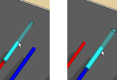
Use a punch component
- Select a round punch component from the building component browser.
- When you move the cursor at a pipe in the IFC model, the component is locked to move in the direction of the
pipe's longitudinal axis. To detach the component from the pipe, press the Alt key and move the cursor over
another pipe. The diameter of the component changes according to the pipe. The tolerance set in the properties
of the component is added to the diameter.
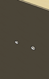
- Select a location for the component. You can see the hole created when you hide the component.
- You can edit the tolerance afterwards by editing the properties of the component.
Note:
- This method allows you to quickly add holes when there are a few pipes.
- The holes are generated only on sheathing parts.
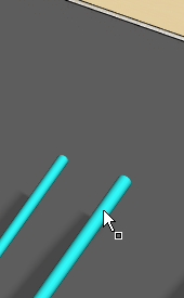
Use the Add Punch to Structure function
- Select the pipes.
- Right-click to open the context-sensitive menu.
- Select Add Punch to Structure.
- Select the structure (panel).
A dialog box appears showing the diameter of the pipe and the diameter of the hole.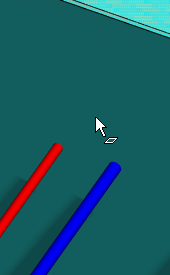
- Enter the diameter of the hole or holes.
- Confirm by clicking OK.
Note:
- This method is suitable if there are a large number of pipes. You can select all pipes at once, and then select the function from the context-sensitive menu.
- The holes are generated for both the frame and sheathing parts.
- You cannot edit the tolerance afterwards.
- This corresponds to the function Generate Utility Holes.
- The holes can be removed using the function Remove Utility Holes.