
Text and Dimension Properties
Define the text and dimension properties in the dialog box. They include for example text content, dimension value tolerance and dimensioning accuracy. Part numbers and engineering drawing symbols are also texts. The features are available depending on the element.
Tab: Text
- Editing a Text
- Enter the text content in the Text field.
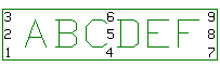
- Center alignment point
- Select the text’s insertion point with the selection circles surrounding the text field. If you want the insertion point to be in the middle of the text field, mark the Center alignment point checkbox. There are nine insertion points as seen in the figure below.
- Enter as line break
-
When you want to add a line break by the Enter key, select Enter as line break. Close the dialog box and add the text by clicking the OK button.
When you want to close the dialog box and add the text by the Enter key, clear the check box Enter as line break. Add a line break to text by pressing Ctrl+Enter.
- Text Number Increment
- Sets the automatic text number increment in use, when the check box is selected and the Increment step specified.
 Underline
- Add a part of the text as underlined. Click the button and type the underlined text in the Text window.
- The underline mode stays in effect. When you want to continue typing the normal text, click the button
 .
. - When you want to add the entire text as underlined, select the property
 Underlined for the text.
  Edit Text Properties
- No underline
- Restore underline text to normal by clicking the button.
 Framed Text
- Add a part of the text as boxed. Click the button and type the text to be boxed in the Text window.
- The box mode stays in effect. When you want to continue typing the normal text, click the button
 .
. - When you want to add the entire text as boxed, select the property Boxed for the text.
- Edit Text Properties
- No box
- Restore the boxed text to normal by clicking the button.
- TED dimension i.e. theoretically exact dimensions
- Add the box belonging to a TED dimension by selecting
 in the text where you want the box to begin and
  to the point in the text where you want the box to end.
  Mark a dimension figure
- By default, the software interprets the first value as the dimension figure that is updated after changes. If you wish that the updated figure is some other one, mark it with special characters. Use the button on the left to mark the dimension figure’s beginning and the
 button on the right to mark the dimension figure’s end. This enables for example entering numeric prefixes to a dimension value.
 - Special character
- Add a special character to be inserted in the Text field contents. Click the button
 and select a special character. The character will be added on the cursor position.
 - Dimension value
- Restore the previous dimension value in the text field, if you have deleted it.
- Drives geometry
- Defines a dimension to act as a geometric constraint. You can edit the geometry by editing the numerical value of the dimension constraint in the Text field. The dimension added to the intersection point of lines will not be updated and cannot act as a constraint, when the geometry is changed.
- Fake dimension
- Defines the value for the dimension figure as permanent. You can specify a value for a dimension that differs from the actual value. You cannot use this feature for dimensions that act as constraints. When the geometry is changed, the extension lines will be updated only, not the dimension figure.
- Controls eave height
- Vertex BD: Select the property for a distance constraint defining the roof overhang on the side eaves.
- Arrows
- Automatically (default) defines the dimension arrows based on where you click the dimension position on the dimension line. Change the dimension arrows to Inside or Outside by clicking the selection button.
- Tolerance
- Defines a dimension tolerance to be added to a dimension. You can add a tolerance in the field in the following ways.
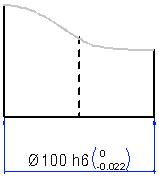
- Tolerance symbol
- If you enter the tolerance symbol in the Tolerance field. The program will also add deviations to the dimension figure.
- For example, h6.
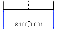
- Deviations
- You can enter deviations in the Tolerance field in the following ways.
- +-0.001
- 0-0.04
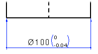
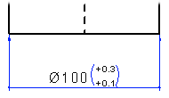
- By adding a space between the upper and lower tolerances, you can present the tolerance mark in parentheses. For example: +0.3 +0.1
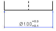
- By adding a comma between the upper and lower tolerances, you can present the tolerance mark without parentheses. For example: +0.3,+0.1
- Tolerance symbol
- Quality
- Defines the dimensioning precision, the decimal precision of the dimension.
 Editing the Dimensioning Precision of Dimensions
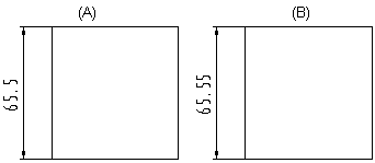
- Inch conversion
- Defines the precision of the inch conversion of a dimension. Inch conversion is dimension-specific. Select the appropriate precision in the Inch conversion list.
 At this point, the dimension is not yet changed to the inch dimension.
- Convert Dimensions to Inches
- Formula
- Defines the variable of the dimension figure.
- Unit
- Select the unit for metric dimensions from the list:
- mm
- cm
- m