
Add a Handle
You can add a handle to a part. The handle will act as the part's reference point when it is added to an assembly, for example. Add a handle to a part as follows:
- In the model window, select the context-sensitive function .
- Select
 Insertion points.
 - Select Add.
- From the part, select the point to which you wish to add a handle.
- Fix the handle's Z-direction by selecting a planar surface from the part. The plane's normal will be set as the handle’s Z-direction.
- Fix the handle’s X-direction by selecting a planar surface from the part or accept the current direction by selecting the context-sensitive function
 OK or by pressing the middle mouse button. The normal of the selected surface will be set as the handle's X-direction. Notice that the direction is determined only based on the component that is perpendicular to the selected Z-direction.
 - Enter the handle’s Label into the Macro location dialog box.
- If necessary, move or rotate the handle in the Macro location dialog box. Relocating
- Select OK.
During steps 4, 5 or 6 you can select auxiliary functions from the model window's upper left corner so that you can position the handle precisely how you want. You can limit the cursor snap so that you only select points, center points of lines, surface points or planar surfaces. You can define the handle's location by selecting a point. The direction can be defined by selecting either two points so that the direction is a vector from the first point to the second, or by selecting a planar surface so that the direction is the normal of the surface.
You can add a handle faster if the directions of the handle axes do not need to be defined precisely. Add a handle faster as follows:
- From the part, select the point to which you wish to add a handle.
- Select the context-sensitive function Add Handle.
- Fix the handle's Z-direction by selecting a planar surface from the part. The plane's normal will be set as the handle’s Z-direction.
The Z-direction of the handle matters when a library feature or component is being added to a part or an assembly. Select the Z-direction for the handle as follows:
- Library feature: define the direction of the Z axis of the part's handle to create a cutout feature. When you position the feature on the part, the Z axis of the feature will be set perpendicular to the face of the part. The direction of a boss library feature will be changed automatically when you add it to the part. In parallel projection, the Z axis points in the direction of the arrow.

Figure 1: Library feature (A) and library component (B). - Library component: define the direction of the Z axis of the part's handle so that when you add the component to the part, its Z axis will be set perpendicular to the face of the part. The possibility of setting snapping to faces only is a suitable property for a component's handle, the component snapping only to faces when it is added to an assembly (see Handle Properties).
- Combined library feature: Define the direction of the Z axis so that when you add the feature on a sheet, its Z axis will not be set coincident with the sheet face normal, but in the direction opposite to the sheet face normal.
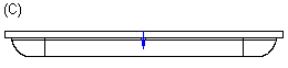
Figure 2: Combined library feature (C).