This function can be used to define feature properties, such as tangency, elements connected to the feature, and torsion. Specify the feature data in the dialog box.
Dialog Box Options
- Add or Delete
- Select adding or deleting loft.
- Tangential Geometry
- Defines the tangency of the loft from one of the following options.
- No tangency - Loft is created without tangency. Compare to the Tangency at ends option.
- Guide curves - The guide curve is a tangential polyline. Each face created during the loft can have an individual guide curve. The guide curve intersects the edge line of the surface.
- When drawing a guide curve, selecting a curve point from the edge line of the face will be easier if you add a reference line to the loft section face with a point on the edge line.
 Use Guide Curves in Lofting
 When you select the tangency to Guide curves, Virtual guide curves, or End surfaces, select the tangential quide curve as follows:
- Select the tangential polyline search clicking the following button:
- Click the first line of the guide curve.
- Select Confirm.
- Alternatively, you can individually select each line of the tangential polyline in order.
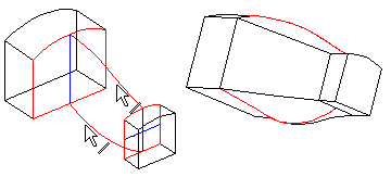
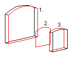
- In the example shown in the picture, tangency uses two guide curves.
- Virtual guide curves - The guide curve also determines the shape of the edge lines of faces created in the loft. Select a guide curve as described in the Guide curves section.
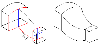
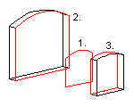
- In the example shown in the picture, tangency uses only one of the guide curves.
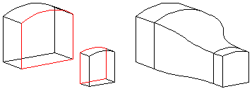
- To end faces - A tangency factor can be specified for tangency to end faces. It affects the shape of the edge lines of faces created in the loft.
- Compare an example of the image to the No tangency option.
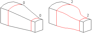
- Tangency factor 1 and 2
- Defines a tangency factor individually for both end faces. You can specify the factor if you have selected the Tangency to end faces option. Define the factor of the end face selected first in the Tangency factor 1 field and the factor for the second end face in the Tangency factor 2 field.
- When the factor value is 0, the edge lines of the loft faces are not tangent to the end face at all. Increase the factor value with small increments.
- Cross sections
- Defines the cross sections based on which the loft feature is modeled. You must select at least two loft section faces for lofting. They can also be the end faces of a volume.
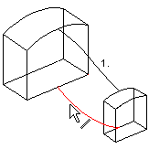
- If you are creating a loft based on more than two cross sections, note the correct selection order.
| Correct
|
Incorrect! |
 |
 |
- Adding, changing, deleting loft section faces and guide curve lines
- View, change or delete selected elements in the loft with the buttons. Select an element from the list and click a button.
- You must select the elements for a loft in the correct order. The selected elements are displayed on the list in numerical order.
- When adding a loft section face in between loft sections already in the loft, select Face N from the list and add the new loft section face in front of it.
- Select a face either of the following:
- Click the context-sensitive Add button and select a face.
- Select an empty row and click the button Add and select a face.
- The lines that are a part of the same polyline are displayed on the list with the same numerical ID. When you add a guide curve to a loft, move the cursor to an empty line in the list, which activates the Add button.
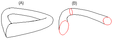
- Closed
- Defines the loft as a closed chain of faces (A), when this checkbox is selected. This function can be selected if three loft sections have been selected at least. This will automatically loft the space between the first and last loft sections. If the checkbox is empty, lofting is performed only between the selected loft section faces (B).
- Rotation
- Defines either deletion of automatic torsion or adds torsion using location points.
- Automatic - This function attempts to delete torsion. Torsion is caused by differences in the shape of the loft section faces. Torsion is deleted by a software algorithm.
- Location points - Location points can be used to delete or create torsion. The location points are automatically positioned in the corner points of the face edge line. In the model, one point per face is displayed.
- View, change or delete loft location points with the buttons, see Twist in Lofting.
- Apply
- Preview by clicking the Apply button. This will show you how the model would look if you confirmed the feature data by clicking OK. If necessary, you can still edit the feature data.
