
Create a Drilling Component
General
- The components needed for the block design drillings are regular models, which are controlled by the dimension table if necessary.
- The components are either drillings or components to be attached to the block, such as valves.
- All components can have machining properties, e.g. the valve makes the fastener holes in the block.
- The entire component can also be a machining part, in which case it does not become a part in the parts list (e.g. drilling).
- The components are stored in the component library.
- For more details, see Save a Part in the Component Library
The following files are associated with the component
- component.vxm - A model file with the geometry of the component.
- component.jpg - A browser image that shows the component in the library.
- Generated automatically when the model is saved
- component_2d.jpg - An auxiliary image where the meaning of the dimension table of the component can be presented.
- This must be done separately and saved alongside the previous ones
Make a drilling component for drilling blocks
- Model drilling geometry.
- In the figure below, the geometry of a simple drilling is modeled in three different steps in the Vertical (XZ) plane.
- The sketches have variables D1, L1, D2, L2, D3 and L3, which control the diameters and depths of the drilling.
- Drilling depths always start from the surface of the block.
- In general, the next diameter should always be given smaller than the previous one, i.e. D1 > D2 > D3 etc.
- If the next depth is smaller than the previous one, no drilling is done with that diameter at all, thus 1 to 3 drillings of different depths with different diameters can be handled in the same place with one component.
-

- Add a grip point to the component at the point which you want to locate on the face of the block when the drill is imported into the block assembly.
- The blue axis of the grip point comes outwards from the surface of the block.
- The grip point will automatically have the Snap to Face Only feature when the block option is enabled. This makes it easier to position the drills, as they automatically turn perpendicular to the surface of the block.
- If the model only presents drilling, change its properties to a tool.
- Select the context-sensitive function
 Properties.
 - Select
 Tool.
Tool. - See Machining Feature
- Select the context-sensitive function
- Open the model item data.
- Select the context-sensitive function
 Item Data.
 - The program opens a two-piece card with the lower part of the card shown below. The upper card is not filled out.
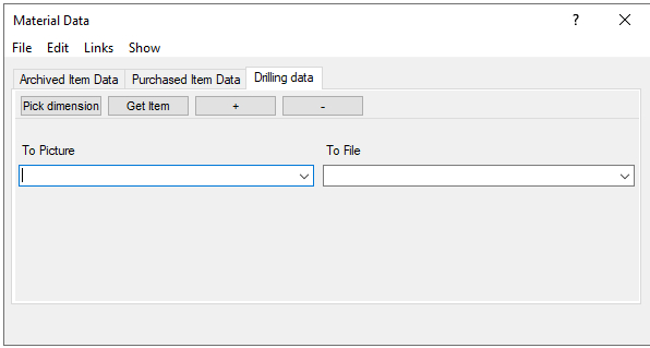
- Select the tab Drilling Data.
- Select the context-sensitive function
- Enter the attribute data that will appear in the drawing and list
- To Picture field, for example: Ø#D1#/#L1#|Ø#D2#/#L2#|Ø#D3#/#L3#
- To File field, for example: D#D1#,L#L1#|D#D2#,L#L2#,D2#D3#,L3#L3#
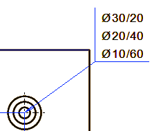
 The information inside the hash marks, for example #D1# or #L3#, is supplemented when the model is varied and can look like the following, for example #D1!30# and #L3!60#
- Accept the attributes by selecting OK in the upper card.
With the attributes of the previous example, the following entry for the feature will appear in the drawing.
Note: