Create a Polar Pattern in a Plane
General
- Create a polar pattern in a circumferential shape or both circumferentially and lengthways.
- If the part to be patterned is positioned with the Parallel constraint from the base plane of the handle (the xy plane), this same plane is used as the default plane of the pattern when creating the part pattern.

Create a Polar Pattern in a Plane
- The instructions describe the creation of the pattern with the context-sensitive function
- Select the part, parts or subassembly from which you wish to create a pattern from the assembly.
- If you select more than one part, hold down the Ctrl key.
- Select the context-sensitive function
 Pattern.
- The program opens the dialog box Assembly Pattern Data.
- Select Polar in the dialog box of the assembly pattern.
- Confirm the location New pattern.
- Select the direction: The direction only matters if the members of the pattern are not equally spaced on a full circle.
- Clockwise.
- Counterclockwise.
- Enter the number of pattern members in the Circle-direction.
- Enter either:
- The angle at which the pattern members are placed, or
- 360 = The members are placed at equal intervals on a full circle.
- Delta, or the angular spacing of two pattern members.
- The angle at which the pattern members are placed, or
- If you want to affect the diameter of the circle of the auxiliary part, enter the Radius of the circle.
- Note that this does not solve for the radius of the polar pattern.
- If you want the polar patterns to overlap, enter in Length-direction:
- The number of overlapping patterns in the Number field and
- The overlapping distance of the pattern members to the Delta field.
- Select OK.
- Click the position of the center point of the circular auxiliary part in the assembly.
- Note that the position of the center point of the guide curve part relative to the part to be patterned solves the radius of the polar pattern.
Example of a polar pattern
- Number in circle-direction 18, Angle 360.
- There is only 1 part in the length-direction (1= default value).

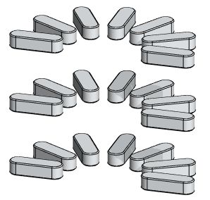
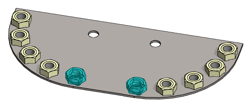
Example of a polar pattern, where there are also parts in the length-direction
- Number in circle-direction 7, Angle 180 (= equally placed on a semicircle).
- There are 3 parts in length-direction, delta 40.

Example of a clockwise and counterclockwise polar pattern
- Number in each pattern 5.
- Angle in each pattern 90.
- The pattern on the left is done clockwise and the pattern on the right is done counterclockwise.

Note:
- You can edit the properties of a polar pattern by selecting the pattern from the assembly tree and then selecting the Edit function.
- You can set the auxiliary part of a polar pattern visible in the model drawing. Select
 Auxiliary geometry visible in drawings as the property of the auxiliary part.
