
The Wall Panel Settings Dialog Box
Framer
When you generate the wall panels or edit the wall panel settings in the component library, select the layers, corner overlap type, label, viewing direction of the panel, and other settings in the dialog box.
Load Default Settings
The wall panel settings have been saved in the component library. When you generate the wall panels, you can select either project-specific settings, customer fitted settings or the system settings of the basic software delivery from the list. The selections in the dialog box are updated according to the selected collection of settings.
If a customer-fitting has not been implemented, system settings are the default.
You can save the panel settings used in this project by clicking Save Project Specific Settings. The settings are saved in the component library in the project folder.
Basic
- Layers
- Select the structural layers to be included in the wall panels. Only the geometry and parts of the selected structural layers are generated in the framing model. The geometry of the structural layers is generated in the framing model when you create the panel breaks. Parts will be created later using a different function.
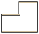
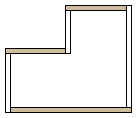
- Corner Details
- Select how the wall panels are cut in corners. Select one of the following:
- Vertical Walls Extended
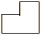
- Horizontal Walls Extended
- Clockwise

- Counterclockwise
- Vertical Walls Extended
- Set Panel Label Using
- The wall panel label consists of a prefix and a sequential number. The prefix can be read from the wall frame parameters or the user can define the prefix in a dialog box. Select either of the following:
- Panel Settings
- You may be using different property sets for wall panels. A property set defines how to number the framing pieces, for example. When you generate the wall panel breaks, you can select the property set to be used for exterior and interior wall panels in the Wall panel settings box.
- Interior view
- The default viewing direction of a front projection created in a wall panel drawing is from outside of the wall. The panel labels are added to the outside of the wall in a floor plan drawing. If you wish the viewing direction to be from inside the wall, select the Interior View checkbox. The panel labels are added to the inside of the wall in a floor plan drawing.
- Leave out layers which don’t have framing tools
- When the setting is enabled, the program will find the outermost and innermost layers with a framing tool. These layers and all layers between them will be included in the wall panel. Other layers will be left out of the wall panel.
Advanced
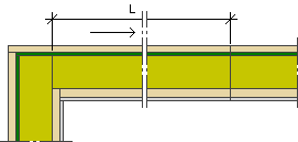
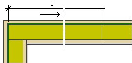
- Wall 1st Panel Length by
- The setting is relevant when the maximum length and default length of wall panels are defined to allow one wall to include several panels. The default lengths are defined in the project parameters.
- Exterior Sheathing - The length of a wall panel (L) is calculated from the end of the exterior sheathing layer closest to the frame layer.
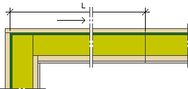
- Structural Frame - The length of a wall panel (L) is calculated from the end of the frame layer.

- Interior Sheathing - The length of a wall panel (L) is calculated from the end of the exterior sheathing layer closest to the frame layer.
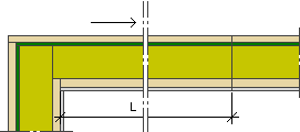
- Exterior Sheathing - The length of a wall panel (L) is calculated from the end of the exterior sheathing layer closest to the frame layer.
- Drawing-Model Pair
- Select the drawing-model pair to which you wish to create the wall panel geometry. The default is Framing.
 Open a Drawing-model Pair of a Frame
- Wall 1st Panel Extra Length
- The final length of the first wall panel is the default length + the length offset. You can define the length offset for held back and extended corners separately. Enter the desired value in the field. The value can be negative, in which case the length offset is deducted from the default length of the panel.
- At Held Back Corner: L = default length + length offset for a held back corner.
- At Extended Corner: L = default length + length offset for an extended corner.
- At Held Back Corner: L = default length + length offset for a held back corner.
- Panelization Direction
- Select the direction in which to rotate the walls and add the panel break points. The panels are numbered in sequence according to the selected direction, if you select to panel all of the walls at the same time.
- Set Layer Thicknesses by Framing Rule Definitions
- In conjunction with the creation of the wall panel breaks, the program checks the compatibility of the wall layers and the framing tools selected for them. If necessary, the program changes the layer thickness to suit the selected tool. If the setting is disabled, the program will only issue a warning but will not change the layer thickness.
- Do Not Cut Panel on Openings
- When the setting is enabled, automatic wall panel break points are not added at openings. The break point is positioned at the given minimum distance from the edge of an opening.
 If break point macros have been added to the floor plan, the program takes them into account before adding the automatic break points. A break point macro can be located even next to or in the middle of an opening.
- Add a Wall Panel Break Point
- Panel Cut Min Distance From Opening
- Automatic panel break point is positioned at the given minimum distance from the edge of an opening, when Do not cut panel on openings is selected, and break point macros have not been added next to or in the middle of an opening.
- Add a Wall Panel Break Point
Batten Settings
- Cladding battens
- The settings can be selected when the Cladding battens layer is selected to be included in the wall panel. The layer can be either an air gap or layer for which no other horizontal batten or sub frame tool has been defined. If the siding is divided into sections (for example, vertical-horizontal-vertical), the program will also divide the batten layer into matching sections. Select one of the following as the direction for the battens:
- Framing Tools Dialog Box
- Double Furring
- The settings can be selected when the layer Double cladding battens is selected to be included in the wall panel. The extra layer is a layer behind the cladding battens. Select the direction and settings as you would for the cladding battens.
- Merging a Wall Volume with a Wall Layer
- Merge Compatible Furrings
- This setting is significant if you have selected the layers Furring Strips and Double Furring (in the Basic tab) for the panel. If the siding is divided into sections (for example, vertical-horizontal-vertical), the program will also divide the furring layer and extra layer into matching sections. If the setting is enabled, the program will merge the extra layer pieces automatically, if they are compatible. The pieces are compatible when the same framing tools have been selected for them.
- Merging a Wall Volume with a Wall Layer
- Add Battens Behind Wall Trims
- If the siding has been divided into sections by a trim, the setting will stretch the batten layer to reach under the siding trim as well. The program tries to stretch the layer according to the vertical siding. If the siding trim is located between vertical sidings, the batten layer of the lower siding will be stretched under the siding trim.
- Shrink Battens by Air Gaps
- When the setting is enabled, the air gap restricts the shape of the batten layer. The shape of the layer is determined by the intersection of the batten area formed based on the sidings and the air gap. This requires that the batten area and the air gap overlap each other at least 60 %.
Corner Details
- Corner Details
- Select the corner and edge details for different wall types.
- Once you have generated the panels, you can still change the corner detail for an individual corner by using the function Modeling | Connection |
 Joint
Joint  Plane Structure
  Corner Details.
 - Corner Details
Attach
- Attach to Element
- You can select whether windows, doors or opening trims will be attached to the panels. Select one of the following to each component type:
- No - Parts will not be attached to the panel and they will not be shown in the panel drawing views.
- Yes - Parts attached to a panel are hierarchically collected under the panel. You can show the parts in the panel drawing views as follows:
- Windows and doors - Open the view properties, select the tab Options, and select Show openings.
- Opening trims - The trims will be added to the view as a layer of their own. Open the view properties. In Filter, select the options Layer filter, and click Settings. The exterior trims are in the layer number 99, the interior trims in the layer number -99. Select the method of presentation of the parts from the Parts list.
Edit the View PropertiesYou can add a schedule of the attached parts to the panel drawing, for example a schedule of opening trims. Add a view to the panel drawing, select the view type Schedule, and select Opening Trims from the list.
- Visible - Parts will not be attached to the panel, but you can show them in the panel drawing as external parts, when the property Show External Parts has been selected for the view.
- IFC Property Sets
- You can attach property data to be exported to an IFC file to components. A standard property set for profiles, sheets, insulations, joist hangers, windows and doors is included in the basic software delivery. You can also define property sets of your own for components.
- Save a Model to an IFC File