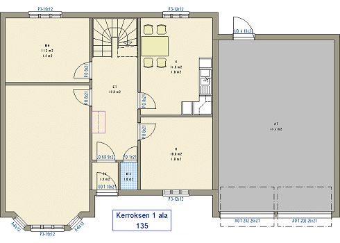
Floor Plan With Color Fills
You can create a clearer floor plan by using color fills. You can select a color fill for walls, rooms and macro components. The color fills are displayed in the floor plan when the Show Color Fills setting has been enabled and the color fill layers are on. Enable Show Color Fills as follows:
- Select
 >
>  Preferences
 Drawings, Models.
 - Select the View tab.
- Select Drawing:
 Show Color Fills.
Color fills are added on their own layers, and you can turn them on and off by toggling the visibility of the layers. The easiest way is to select a layer group in which all color fills are set visible and all extraneous wall lines, e.g. insulation, hidden. You can select the "Sketches color fill" layer group, which is part of the basic software delivery, or create your own layer group by editing the system settings.

Wall color fill
You can select a color fill for a parametric wall. The wall color fill is displayed in the floor plan when you select the Add Color Fill parameter for the wall. The color has been defined in the system settings with the hatch name WALL.FILL. The color fill is added to layer 31.
Room color fill
The color fill of the room is determined by the room label. The program will automatically add rooms based on the walls in the floor plan when the Automatic rooms setting has been enabled. You can then edit the labels of each room by double-clicking it. If the Automatic Rooms setting is not selected, you can define the rooms individually.
The default color fill related to the room label is defined in the system settings. The color is either an RGB color or a pen color, depending on the customer fitting. The color fill is added to layer 56.
Macro component color fill
The color fill of a macro component is defined in its 2D drawing. The drawing can be one automatically generated by the program from a top view projection, or you can use the 2D drafting functions to create the drawing yourself. You can also create the drawing directly from the part model.
The drawing automatically generated by the program can be just a line drawing or a line drawing with a color fill. The color fill is determined by the rendering material or color selected for the component's 3D model. You can enable this option by setting AUTOMATICSH as the macro component's 2D symbol in the component library.
You can define a color fill for your own drawing by adding a hatch to an area enclosed by a closed polyline. Add two hatches:
- Covering Hatch. A simple line hatching is sufficient for the covering hatch. Add the hatch to layer 101.
- Color Fill. Add the color fill for fixture on layer 59, and the color fill for furniture on layer 149.
