
The Wall Dialog Box - Selecting a Wall
You can select the properties of a wall being added or edited in the Wall dialog box. The title bar of the dialog box displays the name of the selected wall. You can accept the default wall properties or select the desired layers for the wall, and their properties. The wall added last is the default.
Dialog Box Options
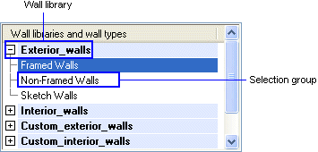
- Wall libraries and wall types
- You may have several libraries available. The walls are grouped by selection groups in the libraries. Select a library and selection group from the list at the top left corner of the dialog box. You can search for a library by activating the list box and pressing Ctrl+F. Enter the desired character string in the text field. If you wish to collapse or expand all libraries, right-click to open the context-sensitive menu and select Expand all or Collapse all.
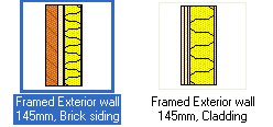
- Wall
- Select the thumbnail image of a wall in the bottom left corner of the dialog box. You can search for a wall by activating the list box and pressing Ctrl+F. Enter the desired character string in the text field.
- Wall Parameters
- Wall parameters are available for selection when you have made a wall thumbnail image active by clicking, and no layer is selected in the Layers list or the preview image. If necessary, deselect a layer by clicking an empty space in the Layers list.
- Color fill for whole wall - When this check box is ticked, the wall's color fill will be displayed in the floor plan. All layers will then have the same color fill. Select the type of the color fill from the list. The type properties (layer, pen, scale, color) are defined in the wall library. If necessary, you can change the color by selecting a new color from the list. The color fill is usually added to layer 31.

When this check box is empty, the color fill for the whole wall is disabled. However, you can define individual color fill parameters for each layer. These color fills will be displayed in the floor plan when the color fill for the whole wall is disabled.
 The color fills will be displayed in the floor plan when the Show Color Fills setting is enabled:
- Select
 >
>  Preferences >
  Drawings, Models.
 - Select the View tab.
- Select Drawing: Show Color Fills.
- Select
- Use project default heights - When this checkbox is ticked, the height positions of the top and bottom edges of the siding and framing layers are read from the project parameters. Other layers retain their height in relation to the framing layer.
- Bearing - When this checkbox is ticked, the layer is load-bearing. This information is required in wall panel design.
- Color fill for whole wall - When this check box is ticked, the wall's color fill will be displayed in the floor plan. All layers will then have the same color fill. Select the type of the color fill from the list. The type properties (layer, pen, scale, color) are defined in the wall library. If necessary, you can change the color by selecting a new color from the list. The color fill is usually added to layer 31.
- Layers
- The default properties of the layers of parametrized exterior and interior walls are defined in the wall library. If necessary, you can select the type, material, thickness, and the bottom and top heights for each layer. You can add and delete layers, move a layer depthwise to the wall, or divide a layer into two parts in the vertical direction.
 A wall must always have a frame layer.
- Layer Parameters
- Layer parameters are available for selection, when you have selected a layer in the Layers list or in the preview image.
- Color Fill - Color fill for a layer is enabled when this checkbox is ticked, but it will only be displayed in the floor plan when the wall parameter Color Fill for Whole Wall is not selected. Select a color from the list, or select a pen color or RGB color in the dialog box (list options Add or RGB).
The color fills will be displayed in the plan when the Show Color Fills setting is enabled.
- Select > Preferences > Drawings, Models.
- Select the View tab.
- Select Drawing: Show Color Fills.
- Select
- Can Be Stretched to Roof - When this checkbox is ticked, the layer can be stretched to a roof above it.
- Color Fill - Color fill for a layer is enabled when this checkbox is ticked, but it will only be displayed in the floor plan when the wall parameter Color Fill for Whole Wall is not selected. Select a color from the list, or select a pen color or RGB color in the dialog box (list options Add or RGB).
- Log walls, foundation walls, other walls
- The properties of log walls, foundation walls or space divider walls are not divided by layer; you will always select the properties for the entire wall structure.
- Pick
- You can select a wall in the building by clicking the Pick button. Click a wall in the drawing or in the model. The dialog box will not reopen; you can directly continue using the wall adding or editing function.
- Plan / Model preview
- The model and floor plan presentation of the wall are displayed in the preview windows. The model is either coarse or accurate, depending on which presentation method you used last when adding a wall. The coarse and accurate models of a wall may look different, because different surface materials may have been defined for the layers of coarse and accurate models in the wall library. You can change the presentation method of the model in the preview window as follows:
- If the model disappears from the preview window, click the button at the top of the window:
 . It will zoom to the extents of the model so that all geometry is within the limits.
 - Select framing, Framing
- These features are available when using the non-layered panelizing method. If a Framing tool has been selected for even one layer of the wall, the features are disabled. See Select a Framing Tool.
Note:
- When you exit the dialog box by clicking the OK button, the selected parameters are made default values.
- You can edit the wall data during the clicking of wall points by selecting the function Select Another Wall. Select the function from an auxiliary menu.