
Truss Parameters
Architectural, Framer
Select the truss parameters in a dialog box.
Dialog Box Options
- Select
- You can select a standard truss or a frame truss by clicking the Select button. After this, you can select the shape-specific parameters. If necessary, you can edit the parameters by clicking the Params button.
 Standard Truss Parameters
- Frame Truss Parameters
- Parameters
- Edit the shape-specific truss parameters by clicking the Params button, if necessary.
- Standard Truss Parameters
- Frame Truss Parameters
- Thickness
- Type the truss thickness in the field.
- Label type
- Select from the list or type the desired character string in the text field. The type will be used as the prefix of the truss labels created later.
- Use
- Select from the list. The options on the list are customer-specific.
- Spacing
- Type the truss spacing in the text field.
- Offset first truss
- Enter the offset (d) from the clicked start point of the truss line for the first truss. The offset is measured to the edge or center of the truss, depending on whether the auxiliary function for fitting the truss is used or not when adding the truss area.
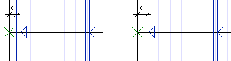
 = clicked point of truss line
- Truss Adjustment
- Offset last truss
- Enter the offset (d) from the clicked end point of the truss line for the last truss. The offset is measured to the edge or center of the truss, depending on whether the auxiliary function for fitting the truss is used or not when adding the truss area.
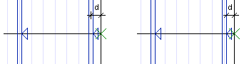
- = clicked point of truss line
- Truss Adjustment
- 2D visibility
- You can make the truss visible in 2D drawings by clicking the 2D visibility check box. Select either Line or Box as the method of configuration. 2D properties define the line drawing properties in the 2D drawing. The property set needs to be defined in the GEOMPROP keyword group in the system settings.
- 3D visibility
- You can make the truss visible in 3D models by clicking the 3D visibility check box. Select either Line or Volume as the method of configuration. 3D properties define the line drawing properties in the wire frame model. The property set needs to be defined in the GEOMPROP keyword group in the system settings. The Surface properties determine the surface color in the shaded model. The color needs to be defined in the d_LWMAP database.
- Ply
- You can add the trusses as single, double or triple trusses. Select one of the following from the list:
- Function
- The parameter is used to export truss information to an external truss design software. Select one of the following options:
- Structure
- The parameter is used to export truss information to an external truss design software. Select one of the following options:
- Label
- Select the location of the truss label by clicking one of the following options:
Note:
- You can edit the parameters of the entire truss area with the function Edit the Truss Area Parameters.
- You can edit the method of configuration of trusses in the model or drawing by editing the truss properties, see Edit the Truss Parameters.
- The default parameter values are defined by truss type in the system settings in the truss.setup keyword group. For example, the label location with the keyword:
param= LBLD x
x may have the following values:- 0 - horizontal
- 1 - center
- 2 - left
- 3 - right