
Hip Trusses: Setback Hip
Framer
You can use this function to create trusses at the ends of a hip roof so that step-down trusses are added to the end. The first step-down hip truss is a setback truss. The location of the setback truss is determined by the selected bearing corner points (exterior corner points of the bearing wall frame) and setback dimension. If trusses have already been added to the end, the program will remove the existing trusses from the area. After selecting the eave at the end, you can select the truss parameters in the dialog box.
Note: There must be a bearing structure at the end of the truss area. This may be either a ceiling selected as a lower limiting structure, or an end wall selected as a bearing wall.
- Select Modeling | Panel |
 Truss
Truss  Hip Trusses
  Setback Hip.
 - Select the truss area by clicking one of the trusses in the area.
- Select the hip end.
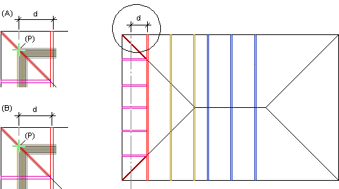
- Click the bearing corner points 1 and 2. Click the exterior corner points of the bearing wall frame (P in the example figure below).
- Select the truss parameters in a dialog box.
- Confirm by clicking OK.
- Select the next hip end.
Hip End Properties
- Setback
- The parameter determines the location of the first hip truss. Type the distance (d) between the truss and the bearing line defined by the selected corner points in the text field. By default, the distance is measured to the edge of the truss (A). If you want to measure the dimension to the center of the truss, select the checkbox Centerline dimensioning (B).
- Girder plies
- You can add the hip truss closest to the edge as duplicated by selecting 2 from the list.
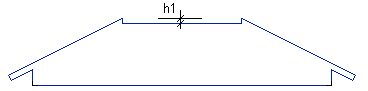
- Hip drop
- h1 = Hip drop. Type the value in the text field, or select one of the options in the list.
- Hip truss spacing
- Type the spacing of the trusses added to the hip end in the text field.
- End truss spacing
- Type the spacing of the trusses added to the edge of the hip end in the text field.
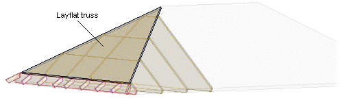
- Add layflat truss
- Select the checkbox, when you want to add a layflat type truss at the hip end. Layflat truss is a triangular shaped truss that is parallel to the slope, and positioned on top of the stepdown trusses.
- Centerline dimensioning
- When this checkbox is selected, the distance between the hip truss and the bearing line defined by the selected corner points is measured to the center of the truss.
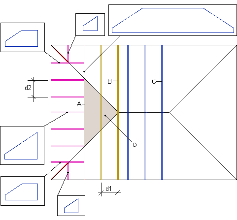
d1 = Hip truss spacing
d2 = End truss spacing
A = 1st hip truss
B = Other hip trusses
C = Primary trusses
D = Layflat truss