
Edit Layers/Default Layers Dialog Box
Edit the layers or the default layer scheme of the active drawing, depending on the selected function. You can rename layers, add or delete layers, change the visibility of the layers in the drawing and in printing and select a color for a layer. You can rename layer groups, add or delete layer groups and select the layers belonging to the layer group.
Edit the Layers of the Active Drawing
Add a layer by selecting Insert new layer from the right-click menu. Enter a number and a name for the layer.
Delete a layer by selecting Delete from the right-click menu.
Dialog box options:
- Layer Scheme
- When you edit the layers of an active drawing, the layer scheme is Drawing specific layers. If the drawing is an imported DWG file, the layer scheme is DWG/DGN imported layers.
- Restore Default Layers
- When you edit the layers of an active drawing, you can restore the layers and layer groups of the default layer scheme to the drawing. You will be prompted: Restoring loses possible drawing specific layer settings. Restore default layers?
- Yes - Drawing specific layers will be replaced with the selected layer scheme.
- No- Drawing specific layers will be retained.
- Insert Vertex layers
- If the drawing is an imported DWG file, you can add Vertex layers to it. After this, you can change the layer scheme of the drawing by selecting either of the following from the list:
- Restore visibility
- When you save a drawing, the data of visible layers is saved into it, if the setting Keep Layer Scheme Saved in Drawing is enabled. Next time you open the drawing, the layers are activated according to the saved information.
- Layer groups
- Edit the layer group names, layers belonging to them and favorite layer groups. See Edit Layer Groups Dialog Box.
- Index
- The layer number.
- Name
- Click the field and edit the name of the layer.
- On
- Set the layer on
 or off
  on the screen.
 - Printing
- Set the layer on or off in printing.
- Hidden
- Hidden layer is a layer, which is always off on the screen and in the printouts. Set a layer as a hidden layer on the screen by selecting the check box.
- Hidden for print
- Set the layer as a hidden layer in printing by selecting the check box.
- Color
- By default, the color of a basic geometry element (line, hatch, text, dimension) is determined by the style selected to it. The style is a set of properties defined in the system settings. If necessary, you can select a color for each layer to be used as the color of all basic geometry elements added on the layer, regardless of their style.
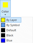
-
Default - The default color of a style or a property set defined in the system settings. Used by default, if you have not selected any other color.
Select one of the pre-defined color options.

 Palette - Select a color from the palette. The colors of the palette are defined in the program's setup file, user/pmap.
Select the order of the colors:
- Hue Order
- Numeric order
Select a new color by clicking from the palette. The old color and the new color selected are displayed in the dialog box. The RGB value of the color is displayed on the right side of the image and its number below the image.
Preview displays the color over which the cursor is on the palette.
Click the Use Default Color button to use the default color of the element, defined in the settings.
- ACI Palette - Select a color from the AutoCAD Color Index palette.
 RGB-palette - Select a color from the palette.
Define a new color by clicking Define Custom Colors. Fill in the color properties, and select Add to Custom Colors.
- In Use
- The layer in the drawing contains objects.
- All
- Set all layers on both on the screen and in printing.
- Clear
- Set all layers off both on the screen and in printing.