
Position References
Use this function to add and update position references in the drawing. A position reference is a text label indicating the position of a certain element in a drawing.
The default position reference format is: <drawing number>:<sheet>/<coordinate>
Those sections (for example, drawing number) that are similar to the current diagram are omitted from the position reference.
Vertex ED: You can add the following position references to the drawing:
 |
To drawing contact chart macros: information about the position of each contact in the drawing. |
 |
Below the device labels of the contact macros of the drawing: information about the location of the active device part of the contact. |
 |
Below the device labels of the cutting reference macros: information about the location of the other cutting reference with the same label. |
Add position references
- On the
 tab, in the Updates
group, click
tab, in the Updates
group, click  Update
Texts.
Update
Texts. - On the tab, in the Update
group, click
 Add position
references.
Add position
references. - You can use old position data or prevent using them as follows:
- Select Yes and the program will not change the entered position references.
- Select No and the program updates all position references.
Reference, which updates the previous and the next occurrences of a cable.
- The reference is added by associating reference text to the cable wire.
- Texts hidden part is the text <ref>:next: or <ref>:prev depending on either
reference is at stake.
The references update only, if a corresponding reference pair exists. Reference to the next includes a corresponding reference to the previous.
Error messages:
If there are errors when adding position references, the program writes them to error log file. For example, error messages are displayed in the following cases.
Vertex ED: For example:
- Undefined contacts are used in the diagram.
- The same contact is twice in the diagram.
- The other end of the cutting reference macro is missing.
 Note
Note
- If the position reference points to another drawing sheet, you can open this sheet in to a new drawing window by clicking the position reference.
- The format of a position reference is defined in settings, in 2D-diagrams/position references.
- Position references create a log file user/wiring_err, which you can open in log browser for viewing. Open the log file Position References in log browser.

Update the position references
If you relocate the component in the drawing, update the position references as follows:
- On the tab, in the Update
group, click Add position
references.
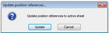
- Select Update.
The update marks modified references and opens a dialog box that is told the amount of changes when an active drawing is updated.
In the Sheet Operations to the log file is entered modification made to the each sheet.
Note
- If adding position references is not possible, make sure that you have saved the drawing after creating it. If you have not saved the drawing, do it and try again.
Minimizing Error Messages of the Position References
When using position references, there may appear an error message caused by the missing active component. You can remove error messages related to active/passive components that appear when updating position references.
You can reduce error messages of position references as follows:
- Select
 Vertex
menu, select
Vertex
menu, select  Preferences, and select Edit.
 - Open 2D-diagrams/Position references.
- Define settings of Message settings for passive parts.
- Confirm by clicking OK.
- Restart Vertex.