
Wiring References
A wiring reference is a text label indicating the point to which a certain connection point is wired. The wiring reference format is:
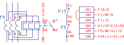
<device label>:<contact label>
If there are several wiring connections at the single connection point, the wiring references to the different connection points will be displayed separated by a hyphen, for example.
K34:11-Q1:14
A wiring reference can be added to all connection points of symbols, and to terminal block contacts type of wiring diagram (type 183) connection points, and to terminal block contacts.
In the device labels of the wiring references of the the terminal blocks is always signs (-, + or =).
Add wiring references:
- On the
 tab, in the Update
group, click
tab, in the Update
group, click  Add wiring
references.
Add wiring
references. - Define the insertion of wiring references.
- Select adding of both wiring references to symbols and terminal blocks by selecting both.

- Select adding to either of the followings: As an example,
 Wiring references to
symbols.
Wiring references to
symbols.
- Select adding of both wiring references to symbols and terminal blocks by selecting both.
- Select OK.
- Select the method of selecting elements and click area limits according to the selected method.
- If you want to add or remove selections, select the
 Selecting Single Elements function and select an element.
 - Select Confirm.
Selected terminal blocks and their wiring references are displayed in a database view.
- Edit the wiring reference information using normal database functions.
 Note
Note
- Updating of wiring references does not ask for terminal blocks if you are completing a wiring schema. Edit the settings, so you get all the wiring references and internal wirings in terminal blocks as normal references to the wiring list. Change the setting as follows: Add Keyword block_wlist_mode = 4 to the setup file.
- Wire references of a cables will be included, if block_wlist_mode= 3 is defined in Vertex
Settings. Reference is in format Device:pin [cable/wire].
 Edit Vertex Settings
 - Wiring references are derived for the wiring diagram symbol either upwards or downwards by default depending on the location of the connection point in relation to the center point of a symbol. In some cases, this automatic control does not work correctly. Then a description text can be specified for the connection point of a symbol in the text editor. The description controls the direction of the reference. Control markings are NO_REFERENCE, not reference at all, or RIGHT, LEFT, UP, DOWN, reference to the specified direction.
- Wire connections between the contacts in a terminal block are drawn by bridging the
adjacent contacts or by adding a connection line between them.

- A wiring reference consists of a connection line attached to a connection point and a text label added to the end of connection line. The properties of a connection line and a text label are defined in settings.
- Default angle of wiring reference texts in 90 or 270 degrees, depending on the location of connection point.
- If you want to make sure the direction of the reference, set the control marking in the symbol editor for the symbol connection point: UP, DOWN, LEFT/RIGHT. Given direction for the connection point is edited when the references are updated, according to the angle and mirroring of the symbol. The control marking can be overrided by giving an attribute WREF_DIR with a value of UP/DOWN/LEFT/RIGHT in the list of common attributes for I/O point. This value is used directly as a reference's angle despite the angle of the symbol.