
Assembly Pattern Data
Define the pattern data in the dialog box.
Dialog Box Options
- Linear
- Defines the pattern as linear. Click the Linear button. You can define a linear pattern in an assembly in either one direction or in both the longitudinal and latitudinal directions. For a linear pattern, define the number of components, either the length (width) or the distance, and the angle at which the components will be set.
 Creating a Linear Pattern in One Direction
Creating a Linear Pattern in Both Directions
Selecting the Direction of a Linear Pattern in an Assembly- Polar
- Defines the pattern as polar. Click the Polar button. For a polar pattern, define the number of components, the angle between components and the radius at which the components will be set.
- Polar Pattern
- Polar with pitch
- Defines polar pattern with pitch. As an example, stairs.
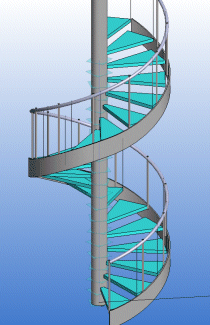
- Pitch
- Defines the value of the pitch.
- No rotation
- An asymmetric component will be rotated in a polar pattern (default). You can prevent rotation of the component by selecting the No rotation check box.
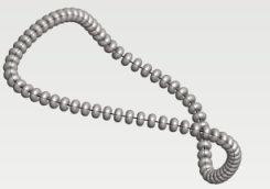
- With guide curves
- Create a part pattern along a line or tangential line chain. Select lines to the Guide curves
- Locating point
- Define a point from the part or assembly that is projected to the line. The default point is the part's or assembly’s origin or handle.
- Number
- Defines the number of components in the pattern. The component based on which the pattern is created is included in the number of pattern components.
- Formula
- Defines a variable for a pattern property, for example number, length or width.
- Length
- The software calculates the line chain length.
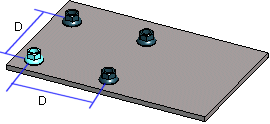
- Scale
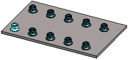
- Defines the distance (D) left between the components in either the longitudinal or latitudinal direction. Example: Define a linear pattern to both directions: 2 pieces of components, distance between them is 50.
- Distance: With guide curves
- If you entered a Delta value, you can choose whether the distance is calculated Along Curves or Straight.
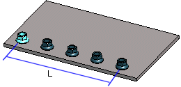
- Length
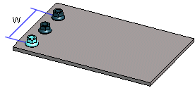
- Defines the length value (L) in the longitudinal direction at which the components will be set at equal distances. The direction of the positive X axis determines the longitudinal direction in the assembly (default). To check the directions of the axes, press the K button to change the cursor into a coordinate axis cursor. If necessary, rotate the pattern.
- Width
- Defines the width value (W) in the latitudinal direction at which the components will be set at equal distances. The direction of the positive Y axis determines the latitudinal direction in the assembly (default).

- Radius
- The radius defines the value of the radius in the geometry, type of guide curve, PATTERNPOLAR. The specified radius value will not affect a polar pattern.
- Angle: Linear pattern
- Defines the angle of a linear pattern. The angle of a symmetric pattern is 90 degrees, but you can also define another value.
- Angle: Polar part pattern
- Defines the angle at which the components will be set at equal distances.
- Deleted
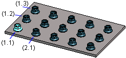
- Defines which components are deleted from the pattern. The position of the component is given as XY coordinates inside parentheses. A period (.) is used to separate the X and Y coordinates. In the Deleted field, you can enter several components to be deleted one after another, for example (1.1)(1.3). The parent component is (1.1). You can define components to be deleted when creating or editing the pattern.

- Deletw a Component from a Pattern
- Edited
- When a feature pattern has been created of a local part, and a part other than the first one in the pattern has been edited, its coordinates are displayed in the Edited field just like the coordinates of a deleted component.
- Edit a Local Part in a Pattern
Replace Edited Local Parts with the Original Part - Pattern Location
- Defines how the pattern is positioned in the assembly. Select one of the following options: