
Create a Linear Pattern in Both Directions
You can create a linear pattern in both directions, lengthways and widthways. Define the number and length or the number and delta.
- Select the component from which you wish to create a pattern from the assembly.
- Select the Pattern function from the context-sensitive menu.
- Select Linear in the dialog box of the pattern in the assembly.
- Create a pattern in both directions. Complement the data for both Length Direction and Width Direction.
- Fill in the Number of the components and their Length or Delta. The number includes the component used to create the pattern.
- The default value for the widthways direction is a ninety-degree angle. If you wish to create the pattern using some other angle value, fill in the Angle field.
- Select positioning the pattern by clicking New Pattern.
- Click OK.
- Before clicking the location of the control part, you can rotate it or click a new reference point.
- Rotate the control part around its axis. The direction of the positive X axis (red) determines the lengthwise direction in the assembly (default). The direction of the positive Y axis (green) determines the widthwise direction.
- Click a new reference point on the pattern part.
- Select a position for the control part.
- Select a point or line of the component for which you wish to create the pattern.
- Select a point or a line from the assembly geometry.

Note:
- You can also create the pattern by defining one direction of the pattern in the dialog box and the second direction by clicking. For example, if you wish to click the lengthways direction (X axis) in the assembly, do as follows:
- Fill in only the Number of components in the Length Direction section.
- Fill in the Number of components and their Length or Delta in the Width Direction section.
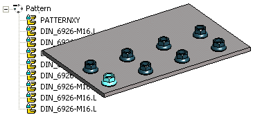
- If you position the pattern using the New Pattern selection, the software will add the
 PATTERNXY pattern part to the pattern. After adding the pattern you can edit the direction and relative positions of the components in the 3D sketch of the control part.
 - You can use a control part PATTERNXY for orientating the pattern and assembly constraint to bind the pattern to other parts of the assembly.