
Edit the Control Part of a Pattern
If the pattern has been positioned using the New Pattern option, edit the directions and relative positions of the components in the 3D sketch of the control part.
- Select the pattern's control part
 PATTERNXY or PATTERNPOLAR.
- Select the context-sensitive function Edit, or double-click the part.
- Double-click 3D Sketch.
- Edit the 3D sketch as follows:
 Do not remove lines in the 3D sketch. Do not remove automatically added dimension constraints.
- Edit the constraints of the pattern.
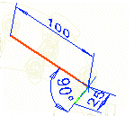
- Edit the length or angle of a linear pattern. Edit the length of the X axis (red) or Y axis (green) with a Distance constraint. Edit the value of the Angle constraint.
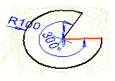
- Edit the angle of a polar pattern. Editing the radius (R 100) will not affect a polar pattern.
- If a longitudinal direction has also been defined for a polar pattern, you can edit its length with a Distance constraint.
If the longitudinal direction is not defined, in the 3D sketch origin point is always the contsraint Distance (1). You can use the guide curve of the longitudinal direction as a help in modeling if you first delete the Drives Geometry property from the constraint.
- Edit the length or angle of a linear pattern. Edit the length of the X axis (red) or Y axis (green) with a Distance constraint. Edit the value of the Angle constraint.
- Edit the constraints of the pattern.
- Confirm the 3D sketch OK
- Accept the control part by clicking the OK button.
Note:
- You can add constraints between the part and the guide curve if you first release the control part PATTERNXY or PATTERNPOLAR.
- If you select a pattern from the assembly tree, you can see the pattern's control part in the assembly model. The length of a linear pattern is along the X axis (red) and the width along the Y axis (green).
