
Projection Settings
Double-click the projection in the model drawing.
 The selected projection define it what settings you can select in the dialog box. For example, if you select the section projection, you can edit the related settings.
Edit the projection settings in the dialog box.
- Projection Name/Header/Scale/Configuration
- Projection (direction)/Show from Model
- Section
- Change the properties of the Quick section cut
- Detail View
- Flattening
- Drawing mode
- Add a Gravity Center symbol to a drawing's projection
- Inser sketch dimensions to projection
Projection Name/Header/Scale/Configuration
- Code
- The name is entered automatically. The name is formed from the name of the model and projection, for example.
- Header
- The title text will be set as the title of the projection. The title is defined when creating a detail view, section view or a new projection. The title text and its position can be edited. You can also leave the title text empty.
 Move Text from a Grip Point
- Scale
- The default projection scale is 1:1. Select a suitable scale. When the projection is a detail view or a section view, the projection scale will be displayed in the title.
- Scale: autofree or autofix – Dynamic projection
- The projection area can be defined so that it is always drawn inside the selected rectangle by using the function
 Continuous line chain. This is useful when the drawing represents a model whose dimensions vary greatly. In this way, the projection stays in the right place at all times, and the scale is defined in such a way that the geometry fits inside the rectangle.
 - If you draw the rectangle with the function
 Rectangle,
  Open Polyline or
  Closed Polyline, the line chain is not continuous. Make the line chain concatenated by usign the line function
  Concatenate. If you wish to hide the rectangle, move the continuous line chain to layer 110 (hidden layer).
 - Concatenate Lines
- You can reduce the size of the projection by reducing the size of the projection line (drag and drop).
- Edit the System Settings
- Configuration
- Select the configuration for the part displayed in the projection. If in addition to the basic configuration (0: Configuration) there are also other configurations, select the configuration which is displayed in the projection to the field.
- Add a Configuration to a Part
- Add a Configuration to an Assembly
- If you select
 Perspective, automatic dimensioning cannot be selected.
Section
- Section Depth
- You can edit the section depth value once you have added a section projection in the drawing.
- Oblique Section
- Select Border Lines
- Indicate the border lines in the projection, and click Confirm.
- Accurate Cut/Quick Cut
- If you select Accurate Cut, the projection will be cut accurately.
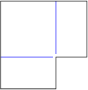
- Select the section line.
- Define a cutting line from the drawing for the drawing's section view.
Change the properties of the Quick section cut
You can set the profiles and pipes valid for dimensioning with an additional setting of the quick section properties. The default value is zero (0) when the high-speed cutting works as in any other geometry. With the value 1 the dimensioning of profiles and pipes is possible. Then the quick section works in such way that the profiles and pipes are cut accurately if they are on the border of cutting area. You can change the keyword value in software settings.
Keyword name: sectionview_pipes_and_profiles
Find a Keyword Among All Keywords
Search a Keyword from a Keyword Group
- Section Hatches
- Add a section hatch to the projection by selecting Section Hatches.
- Section Markings
- Add a mark to the section line by selecting Section Marking at Start and/or Section Marking at End.
- Explosion
- Defines the projection as an exploded view, in which the assembly is displayed as exploded. This requires that the exploded points have been defined for the assembly model.
- Exploded Drawing of an Assembly
- Explode an Assembly
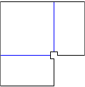
Detail View
Select the shape of the detail view's edge line: Rectangle or Partial MagnificationCircle.
Tools group function Detail View or Circle is not in use in the projection whose drawing method is shaded.
The Header is added automatically if you move the cursor onto an empty field.
Detail View to a Model Drawing
Flattening
Flattening is a configuration of a sheet-metal part. The configuration of a flattening view cannot be changed.
Select the properties of the flattening projection in the dialog box.
- Drawing Simple Geometry
- A flattening projection will only be created from the geometry of a flattening surface selected from a sheet metal part (default).
- Simple Geometry – A flattening projection will only be created from the geometry of a flattening surface selected from a sheet metal part. Also draws the geometry of the forming feature.
 Simple Geometry - The flattening projection will be created by drawing all geometry lines visible in the viewing direction.
- Trim Corners
- Trim Corners – The flattening projection is drawn without corner openings.
- Trim Corners – A corner opening is drawn in the flattening projection.
- Holes Perpendicular
- In practice: the non-perpendicular hole is converted into a maximum size (oval) hole that must be cut into the sheet in order for the shaft or similar pin to fit diagonally through the plate.
- Holes Perpendicular – Holes drawn perpendicular.
- Holes Perpendicular – The holes drawn according to the edge lines of the hole.
Drawing mode
- Drawing mode
- The default drawing mode of the projection in a model drawing is Wire frame, unless another drawing mode was selected when creating a new drawing from the model. You can also select the drawing mode of a perspective projection in the drawing.
- Advanced
- Can be selected for all other drawing mode except Wire Frame.
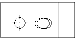
- Exact Silhouette Lines
- The silhouette lines (edge lines) are drawn exactly. Coarse drawing speeds up refreshing the projections, but, for example, the dimensioning of an arc will fail.
- Also for spline surfaces
- Precise silhouette lines (edge lines) are drawn for the part's spline faces.
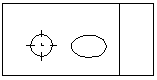
- Center Lines
- Center lines are automatically drawn for circles and arcs. Center lines of the arc will be drawn when the arc sector meets the minimum default value: 180 degrees. You can change the value of the sector projection-specifically. Center lines will be drawn in the projection of a part drawing, even if the Center Lines option is unselected when creating a new drawing.
- You must specifically select Center Lines in the projection of an assembly drawing, if it has not been selected when creating a new drawing of a model.
- The radius is displayed in the projection if Auxiliary geometry is selected.
- Center Lines of Pipe Parts Visible
- The center lines of pipe parts will be visible in the projection.
- The visibility of the pipe part center lines is also affected by the projection property Auxiliary Geometry.
- Hidden Lines
- The hidden lines are drawn with dashed lines.
- Colored Hidden Lines - You can define the color of the dashed lines being hidden in the Settings. Color of Hidden Lines in Drawing Projections
- Auxiliary Geometry
- You can set the auxiliary geometry of a model to be displayed in the projection. Auxiliary geometry is 3D sketches, guide curves, and cross-sections.
- Machining Features
- A machining feature is displayed in the projection if you select Machining Features. The visibility of a machining feature in an assembly has no effect on a projection of a model's drawing.
- Machining Feature
- Gravity Center
- Gravity Center
- Automatic Dimensioning
- You can add dimensions to an active projection of a drawing automatically.
- Automatic Dimensioning
- Tangential lines
- Apparent shape lines will be created between tangential faces. Select drawing as a shape line or thin line, or disable the drawing of tangential lines in the projection.
- Limit from Model
- Limit from Model
- Draw Section Hatches
- Draws a section hatch that is defined as a part property.
- Hatch
- Add sketch dimensions to a projection
- You can set 3D limiting.
- Limit a 3D Model in the Direction of the Coordinate Axes
- Add Sketch Dimensions to a Model Drawing