
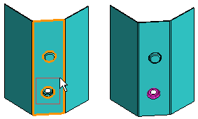
Change a Feature in a Model
A sheet part imported into Vertex may include, for example, a hole or indentation that you want to change.
- Imported sheet-metal/Part model - You can select a Vertex library feature to replace a feature.
- Part model - You can select a library feature to replace another feature. Pay attention to the positioning of the feature.
Note:
- You can change features located on a planar face.
- Feature reference point - When positioning a library feature, the reference point maintains its location. For example, replacing a hole with an indentation keeps the center point in place.
- Feature pattern - The feature change also recognises feature patterns. If the selected faces form a regular sequence, a feature pattern is created automatically.
- If you remove the Feature Change feature from the feature tree, the original feature is restored to the model.
You can change the feature of a sheet part as follows:
- Do either of the following:
- Select at least one feature face.
- Select one or more features to delete along with the area selection. The features to be changed must be located on the same planar face.
- Select +... in the menu bar (Snap).
- Allow searches for a particular element Face.
- Click OK.
- Select the part model in the working window.
- Indicate the closed area. For example, indicate a rectangular area with two corner points so that the indentation is encompassed by the area.
 Select at least the single from the replaceable feature surfaces.
- Select the context-sensitive function Edit> Change Feature.
- Define the properties in the Feature Change dialog box.
- View, change or delete the selected surfaces with the buttons. Select the surface from the list and click a button.
- Select a new feature in the Library Feature field by clicking the Select button.
For example, library features for Import sheets can be found in the Features/Sheet_metal/Special_forming directory.
- Select the feature from the library.
- Click OK.
- Select the feature size or define the values in the dimension table and confirm.
- The new feature is positioned at the center point of the feature to be replaced. If necessary, position the feature using geometric constraints.
- Select
 OK.
OK.